Optimal Working Distance Calculation#
This section defines the recommended Working Distance between the camera and the FlexiBowl’s working surface, together with the resulting selection of lenses required to ensure the correct Field of View (FOV).
The correct choice of the working distance and lens is crucial to:
Ensure that the entire useful surface of the FlexiBowl® is visible
Obtain the resolution required to detect parts
Minimise optical distortions
Facilitate system calibration
Recommended working distances and lens selection#
The choice of lens is strictly dependent on the recommended mounting distance between the camera and the FlexiBowl® work surface. Maintaining the standard working distance ensures the correct FOV and minimises optical distortion issues.
Note
Lens already included
The appropriate lens for the FlexiBowl® model specified in the order is always included in the FlexiVision One packet and is packed separately from the camera. It does not need to be purchased separately.
Distances and field of view diagram#
The following diagram illustrates the relationship between working distance, lens focal length and resulting viewing area for the different FlexiBowl® models.
Diagram key:
Working Distance: Vertical distance between the camera lens and the working surface of the FlexiBowl®
Viewing area: Zone of the FlexiBowl® surface covered by the camera’s field of view
Summary table by model#
FlexiBowl® Model |
Recommended Working Distance |
Lens Included in Kit (Focal Length) |
|---|---|---|
FB 200 |
800 mm |
35 mm |
FB 350 |
1000 mm |
35 mm |
FB 500 |
1000 mm |
25 mm |
FB 650 |
1000 mm |
16 mm |
FB 800 |
1000 mm |
16 mm |
FB 1200 |
1300 mm |
12 mm |
Warning
Importance of the correct distance
Significant deviations from the recommended working distance can cause:
Distance too short: Insufficient FOV (part of the FlexiBowl® not visible).
Distance too long: Insufficient resolution to detect small parts, blurring
Always comply with the distances indicated in the table when mechanically mounting the camera.
Camera Positioning#
Correct configuration. The camera must be positioned centrally and with the same angular orientation as the viewing area of the FlexiBowl® (backlight zone). This way, the field of view (indicated in green) symmetrically covers the entire working area, ensuring the proper operation of the vision system.
Incorrect configurations. The pictures show examples of incorrect positioning of the camera: the field of view (indicated in red) is off-centre in relation to the viewing area, covering only part of the working area or including areas outside the working area. These configurations compromise part identification and the operation of the vision system.
TopLight positioning#
If the system includes a TopLight, its positioning must have the same angular orientation as the camera to ensure uniform lighting. It must be installed on a support that is mechanically independent from that of the camera, so that the camera does not have to be loosened or disassembled to remove or replace the lighting system.
Parameter |
Recommended Value |
|---|---|
Distance from the FlexiBowl® surface |
Similar to the Working Distance of the camera (±100 mm) |
Position compared to the camera |
Concentric (same optical axis as the camera) |
Orientation |
Parallel to the surface of the FlexiBowl® and same angular orientation as the camera (Long side of viewing area - Long side of illumination) |
Relative camera-TopLight height |
Vision optics flush with the Top Light upper surface (leave free access to the adjusting ring nuts of the vision optics) 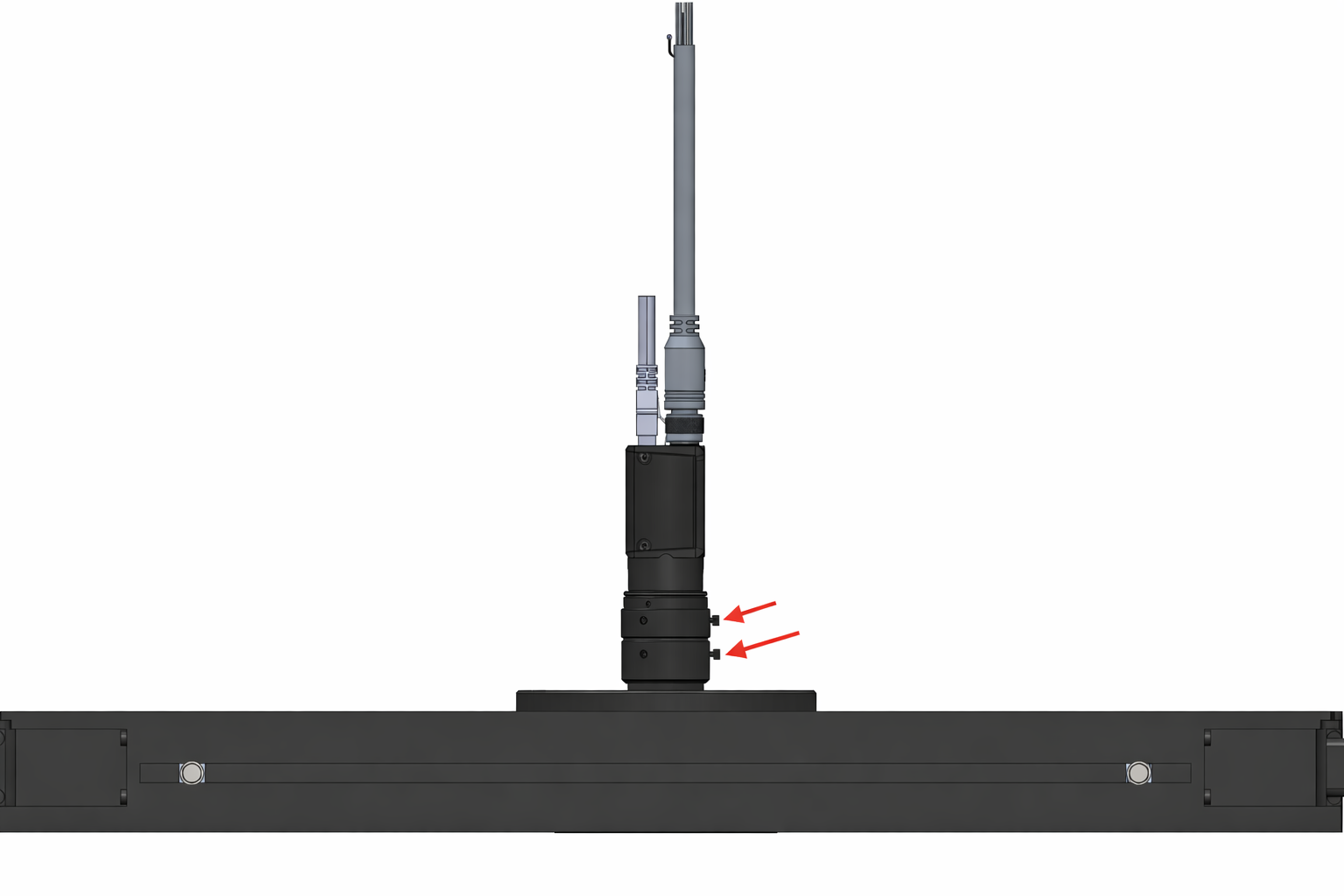
|
Tip
To achieve the best lighting uniformity, follow the indications given above.
Warning
Avoid direct reflections
When positioning the TopLight, make sure that:
Light is not reflected directly from the surface of the FlexiBowl® towards the camera (causing glare)
There are no shadows caused by mechanical components
Lighting is as uniform as possible over the entire useful surface