FlexiBowl® Setup#
This section describes the procedure for connecting and configuring the FlexiBowl® with the FlexiVision One system.
Note
Prerequisites
Make sure that:
Mechanical installation of all components is completed (Mechanical Installation)
All cables are correctly connected (Wiring and Connections)
Access the FlexiBowl® Setup#
1 |
From the software home page, click |
2 |
On the SETUP page, identify and click the FlexiBowl® Setup icon Setup page
|
3 |
The FlexiBowl® Setup screen opens |
 #
#
Connection procedure#
Step 1: Network address configuration#
4 |
Make sure that the address is on the same subnet as the VisionController |
5 |
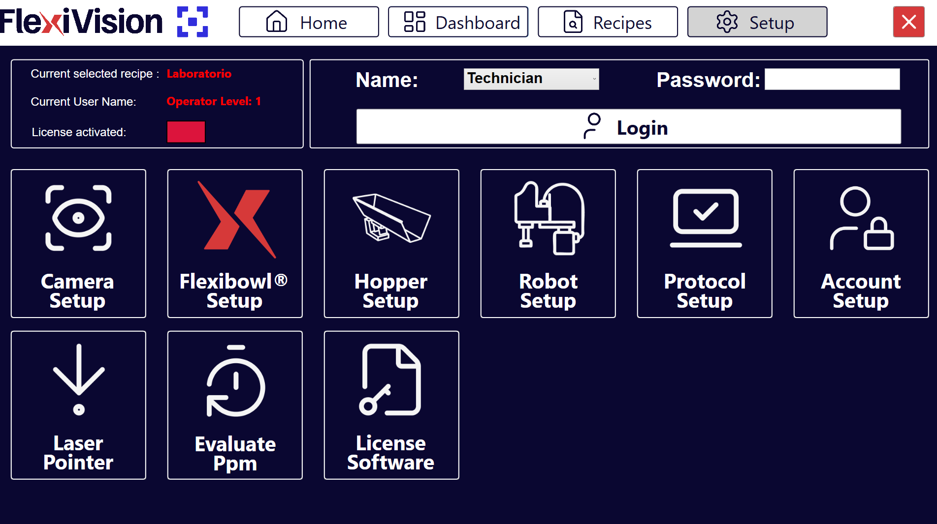
In the field FlexiBowl® IP, enter the IP address of the FlexiBowl®
|
Tip
For the sake of convenience and consistency, start with the first FlexiBowl® available
Note
The FlexiBowl® is shipped with a default IP address 192.168.1.10
Important
For instructions on how to change the IP address of your FlexiBowl®, please refer to the manual available in the Download section.
Step 2: Connection test#
6 |
After entering the IP, click the Connection Test button |
7 |
The system performs a communication test (ping) to the FlexiBowl® |
8 |
Watch the Status indicator:
|
Warning
Connection failed
If the indicator remains red or an error message appears:
Check that you have switched on the FlexiBowl®
Check that the IP address entered is correct
Physically check the Ethernet cable (it must be fully inserted)
If present, check that the network switch/router is on
Ensure that FlexiBowl® and VisionController are on the same subnet
Try pinging the FlexiBowl® from a Windows terminal:
Open Command Prompt
Type:
ping 192.168.1.XXX(replace with actual IP)If the ping fails, it is a network problem
If the problem persists, see Troubleshooting.
FlexiBowl® parameter configuration#
Once the connection is established, proceed to set the operating parameters.
Step 3: Configuration access#
9 |
Click the button |
10 |
A window opens with the configurable parameters of the FlexiBowl® |
Step 4: Parameter synchronisation#
12 |
Click Synchronize Parameters |
13 |
Go back to the main SETUP page to proceed with the next setup |
Warning
Do not skip the synchronisation
It is essential to click Synchronize Parameters after any change is made. Without this step:
The changes are not applied to the FlexiBowl®
The system may behave inconsistently
The settings are not saved
Guided configuration: FlexiBowl® Wizard#
The FlexiBowl® Wizard interface is an interactive tool designed to guide the user in configuring feed parameters according to the specific product family to be managed.
Step 1: Accessing the Wizard#
To start the procedure:
1 |
Go to the |
2 |
Click the FlexiBowl® Setup button. This will open a page with all the FlexiBowl® devices that can be managed with FlexiVision One FlexiBowl® Setup Page
|
3 |
Click the button FlexiBowl® Configuration Page
|
4 |
Click the FlexiBowl® X Wizard button; the Wizard welcome page opens |
5 |
Click Note Click |
Step 2: Model Selection and Rotation#
In this step, the hardware features of the system are defined:
6 |
Select the size of the device (e.g. 200, 350, 500, etc.). |
7 |
Define the direction of disc rotation (Clockwise or CounterClockwise). |
Step 3: Component Characterisation#
The system requires information on the morphology of the parts to optimise separation.
8 |
Select component size:** For FlexiBowl Models 200, 350, 500, 650: <= 150mm > 150mm For FlexiBowl Models 800 and 1200: <= 250mm > 250mm |
9 |
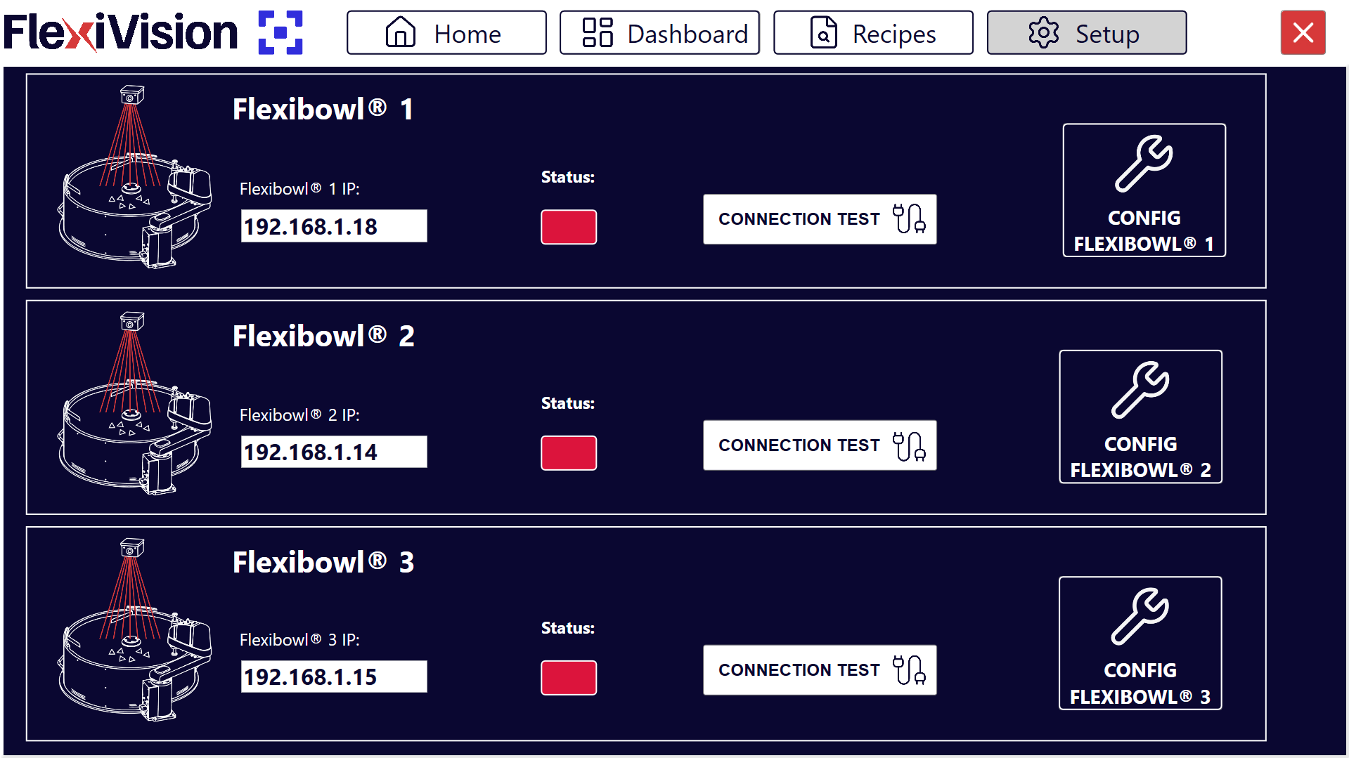
Select the geometry that best describes the component:
Examples of geometries: Flat, Cylindrical and Complex. |
10 |
Define how the components interact with each other on the surface:
Not Overlapping: the pieces do not overlap on the surface.
Stacking: the pieces stack up.
Tangling: the pieces get entangled with each other. |
Step 4: Testing of Accessories#
11 |
Select from the drop-down menu whether the FlexiBowl® is equipped with the Air-blow module. |
12 |
Click TEST Air-blow to check that it works properly. |
13 |
Select USE to enable it in the current application, otherwise click DON’T USE. |
14 |
Click TEST FLIP to check the actual activation of the flip unit. The ‘Flip’ is the unit that generates the mechanical impulse to flip parts; it is essential for separating, untangling or flipping components during the feeding cycle. Important If the pulse is not noticeable, verify that compressed air is connected and adjust the mechanical pressure regulator on the control panel. |
15 |
At the end of the Wizard, clicking FINISH, the system will automatically calculate the parameters:
|
16 |
They can then be fine-tuned in the summary dashboard. |
Group |
Parameter |
Description |
|---|---|---|
Move |
Accel, Decel, Speed, Angle |
Main disc movement parameters. |
Option |
Flip Count, Flip Delay, Blow Time |
Management of accessory activation timing. |
Shake |
Accel, Speed, Angle CW/CCW |
Shake (separation) vibration parameters. |
Step 5: Sequence Validation#
Use the Test Sequence function to check that the cycle meets the following efficiency criteria:
Synchronisation |
The Flip impulse must end at exactly the same time as the movement (Move). Adjust the Flip Count and Delay values to align them. |
Image Stability |
The components must be still when the camera takes the picture.
|
Positioning of pieces during the sequence |
During the movement, the pieces must be conveyed towards the centre of the FlexiBowl® range to maximise the effectiveness of the flip. At the end of the sequence, the pieces should practically be arranged in the centre of the vision area. |
Warning
Always click Synchronize Parameters after any manual change to activate the changes in the controller.
Overview of FlexiBowl® Parameters#
ID |
Element |
Description |
|---|---|---|
1 |
MOVE – Acceleration |
Acceleration value used at each MOVE command |
2 |
MOVE – Deceleration |
Deceleration value used at each MOVE command |
3 |
MOVE – Speed |
Speed value (rpm) used at each MOVE command |
4 |
MOVE – Angle |
Angle at which FlexiBowl® moves at each MOVE command |
5 |
SHAKE – Acceleration |
Acceleration value used at each SHAKE command |
6 |
SHAKE – Deceleration |
Deceleration value used at each SHAKE command |
7 |
MOVE – Speed |
Speed value (rpm) used at each SHAKE command |
8 |
MOVE – CW angle |
Clockwise angle at which FlexiBowl® moves at each SHAKE command |
9 |
MOVE – CCW angle |
Counterclockwise angle at which FlexiBowl® moves at each SHAKE command |
10 |
OPTION – Flip count |
Number of times Flip will be activated |
11 |
OPTION – Flip Delay |
Time (in milliseconds) between an activation and a deactivation of the flip |
12 |
OPTION – Blow Time |
Time (in milliseconds) for activating the blow |
13 |
OPTION – Light on |
Press to enable/disable the backlight |
Tip
Production test
Before using in production:
Run 50-100 test cycles to check consistency
Monitor disk fill rate (it must be constant)
Check that there are no abnormal accumulations or persistent empty zones
Gradually increase to production speed
The ideal configuration may require 2-3 fine-tuning sessions with the actual part in significant quantities.
Next steps#
Once the FlexiBowl® Setup is complete, proceed with: