Creating a New Model#
On this page we will see how to create a reference model for component identification.
Step 1: Preparing the Physical Setup#
If not already done, follow these steps:
1 |
Remove the calibration grid and restore the initial layout:
|
2 |
Place an object in the centre of the vision area |
Step 2: Access to the Model#
Once the physical preparation is complete, proceed with image capture and model creation
3 |
From the “Recipes” page, with the right recipe selected click |
4 |
Select the FlexiBowl® you are working with FlexiBowl® Choice
|
5 |
The available model slots will be shown (up to 8 models per recipe) |
6 |
Click Model 1 to access the “Train Model 1 Cam 1” page |
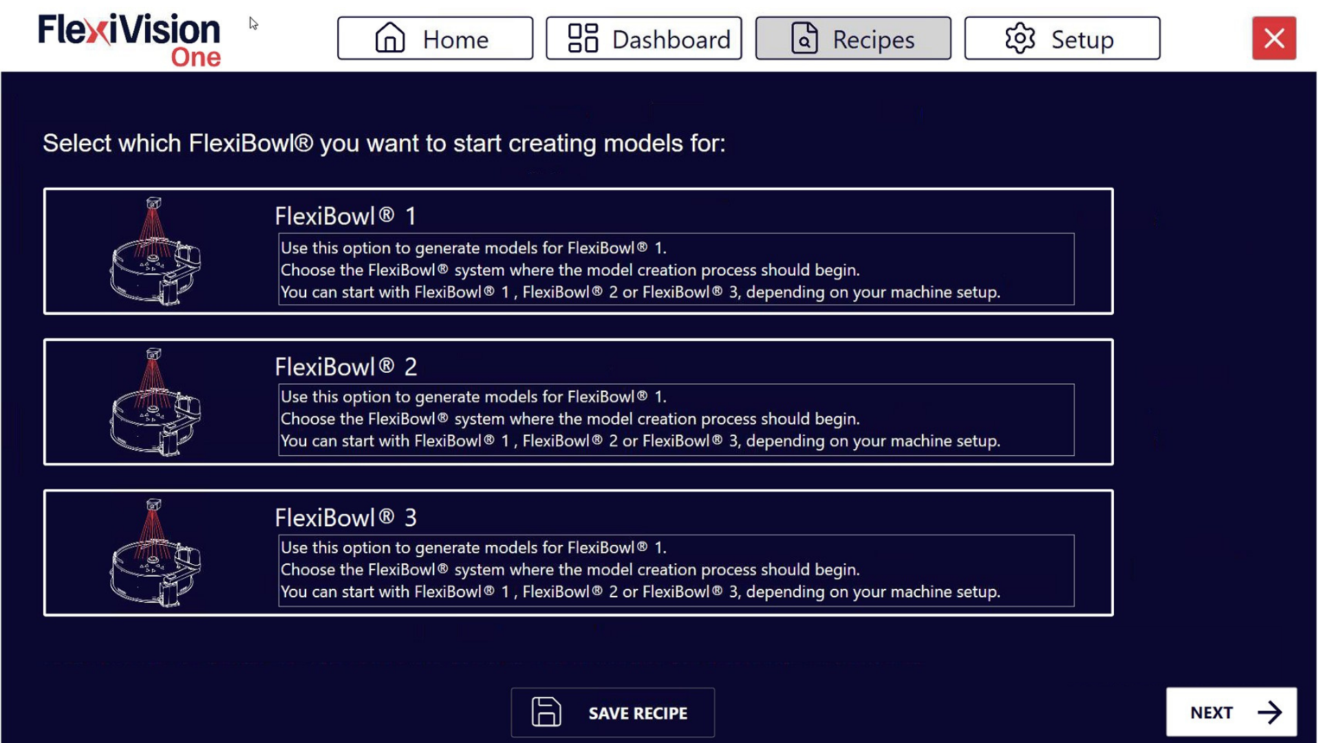
Train Model interface overview#
Parameter |
Function |
|---|---|
Enable Model |
Activates this model slot making it usable |
Grab Train Image |
Takes a picture of the reference component for training |
Score Threshold |
Adjusts the level of detail of the model (from 0 = maximum detail to 1 = minimum detail) |
Train |
Actually generates the model by processing the captured image |
Model Name |
Text field to assign a descriptive name to the model |
Tip
Multiple model management
In this phase only the first model is activated. After completion, you may:
Enable additional slots (Model 2, Model 3, etc.) for different parts in the same recipe
Modify existing models
Disable models no longer required
For the time being, focus on completing the first model.
Step 3: Training Procedure#
7 |
Click Enable Model to enable this model. The model is now active and ready to be configured. |
8 |
Click Grab Train Image to take a picture of the reference component we have placed on the FlexiBowl® Warning The reference component must remain stationary at that point throughout the application creation process |
9 |
Move the ROI box to fully frame the component |
10 |
Move the origin (reference point) to the centre of the frame area Tip Where to position the origin? The origin is automatically placed at the centre of the component. If the pick point does not coincide with the geometric centre, move the origin to the:
The origin defines the (0,0) point of the model coordinate system. |
11 |
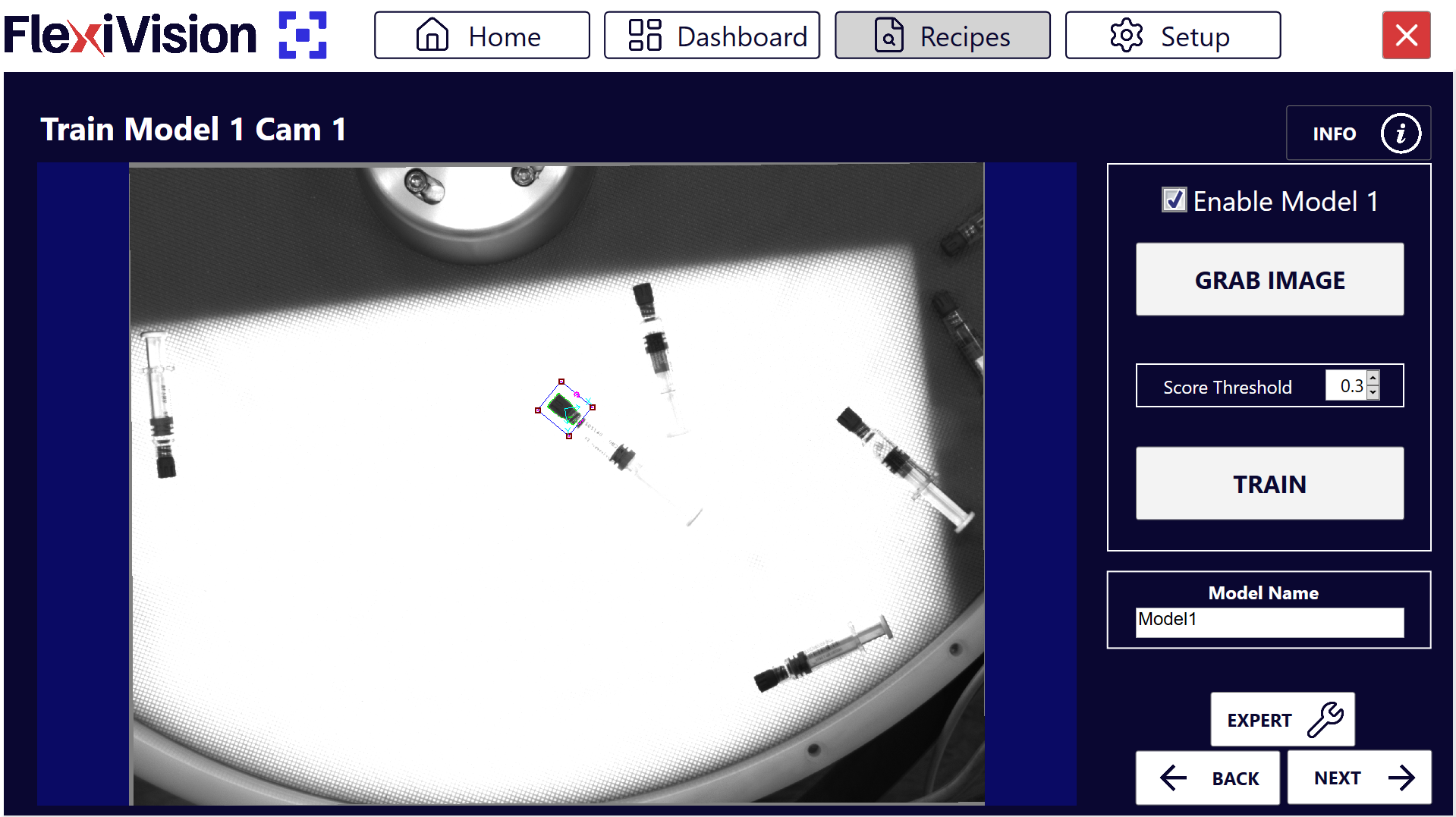
Use the Score Threshold to adjust the desired level of detail Note Score Threshold
Value close to 0 → Detects MORE detail (more precise model) Value close to 1 → Detects LESS detail (simpler model) Tip How to choose the optimal Score Threshold? Use a LOW value (0.1-0.3) when:
Use a HIGH value (0.4-0.6) when:
Use a VERY HIGH value (0.7-0.9) when:
|
12 |
Click Train |
Tip
If you have any doubts during configuration, please consult the INFO key on the current page.
Step 4: Visual inspection#
After generating the model, it is essential to check its quality before proceeding.
13 |
Zoom in on the image to inspect the details of the model created and verify that the model is correct Tip Valid Model Characteristics ✓ Have enough lines to recognise the component ✓ Do not include the texture of the background surface ✓ Avoid light reflections
|
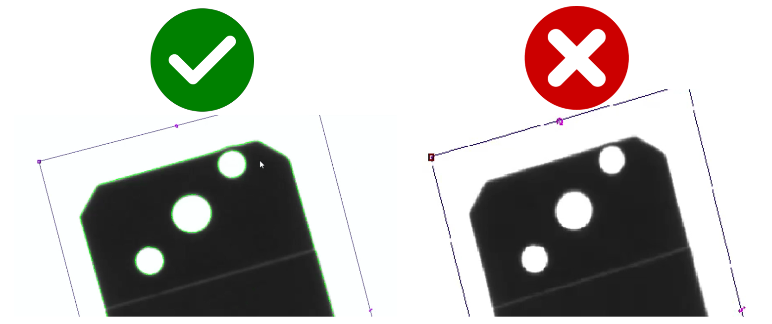
Attention
If the model is not satisfactory:
Edit the Score Threshold
Click again on Train
Repeat until an ideal model is achieved
Tip
Optimisation strategy
Problem: Model includes surface texture → Solution: Increase Score Threshold or Cam Exposure value (SETUP > Camera Setup > Cam Exposure)
Problem: Model has too few lines, not distinguishable → Solution: Decrease Score Threshold
Problem: Model includes reflections → Solution: Increase Score Threshold or adjust camera exposure
Make gradual changes (steps of 0.1-0.2) and test each time.
Step 5: Save#
14 |
Name the model with a descriptive name Tip Avoid generic names ❌ Names to avoid:
✓ Recommended names:
A clear name makes it easier to manage when there are many different models. |
15 |
Click |
 → the Define Robot Pick Area page will open
See also
Proceed to Define ROI to continue configuration.