Clearances#
In this page we will see how to configure Clearances to verify that critical areas are free from obstacles.
What is a Clearance? A Clearance in FlexiVision One is a tool that monitors a specific area of the image to verify that it is clear. It is used to check, for example, that the space required for the gripper to grasp the component is not occupied by other objects.
Note
Operating Principle.
The Clearance analyses greyscale changes in a defined area:
🟢 Green → Area clear (OK for picking)
🔴 Red → Area busy (presence of obstacles)
Attention
The use of Clearances varies according to the part whose model is being made. This assessment is the responsibility of the person in charge of creating the application.
Step 1: Physical Setup#
Danger
Caution! We will show you the procedure with the Gripper Tool, as it requires the configuration of Clearances for models. Other Tools for the robot may not need the Clearances to simulate the footprint.
1 |
From the robot pendant:
|
2 |
Simulate a pick:
|
3 |
Place two objects at the sides of the gripper to have, once the robot is removed, clear areas between the reference component and the two objects. They will represent the robot gripper’s footprint areas. Important Leave the objects slightly farther apart than necessary to avoid errors when creating the model. (2-3 mm margin) |
4 |
Record the coordinates:
Important Record these coordinates! They will be essential during the robot calibration phase. |
5 |
Move the robot away with the pendant without moving anything on the surface |
Tip
If you have any doubts during configuration, please consult the INFO key on the current page.
Step 2: Accessing the Clearance page#
6 |
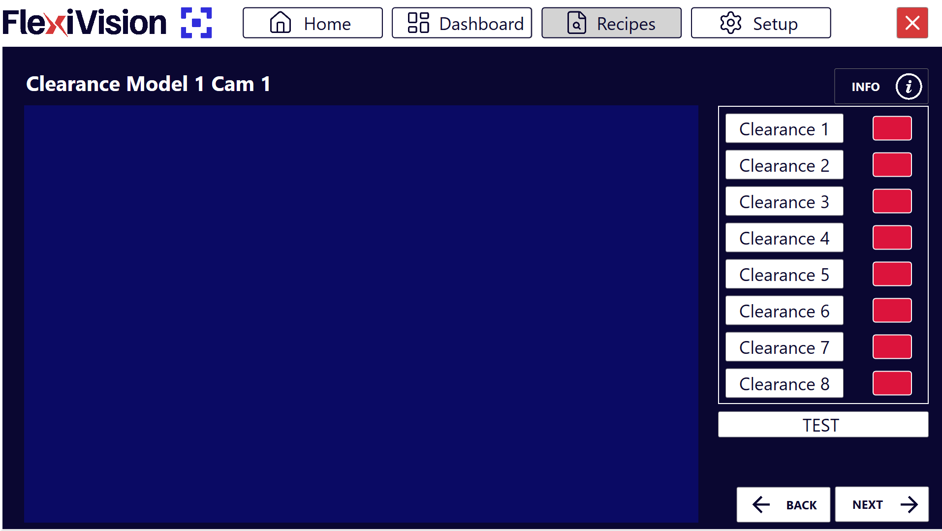
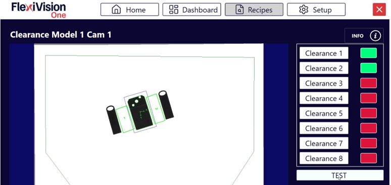
From the Locator Model page, after clicking Next, the list of available clearances (up to 8 per model) will open. Clearances Page
|
||||||||||||
7 |
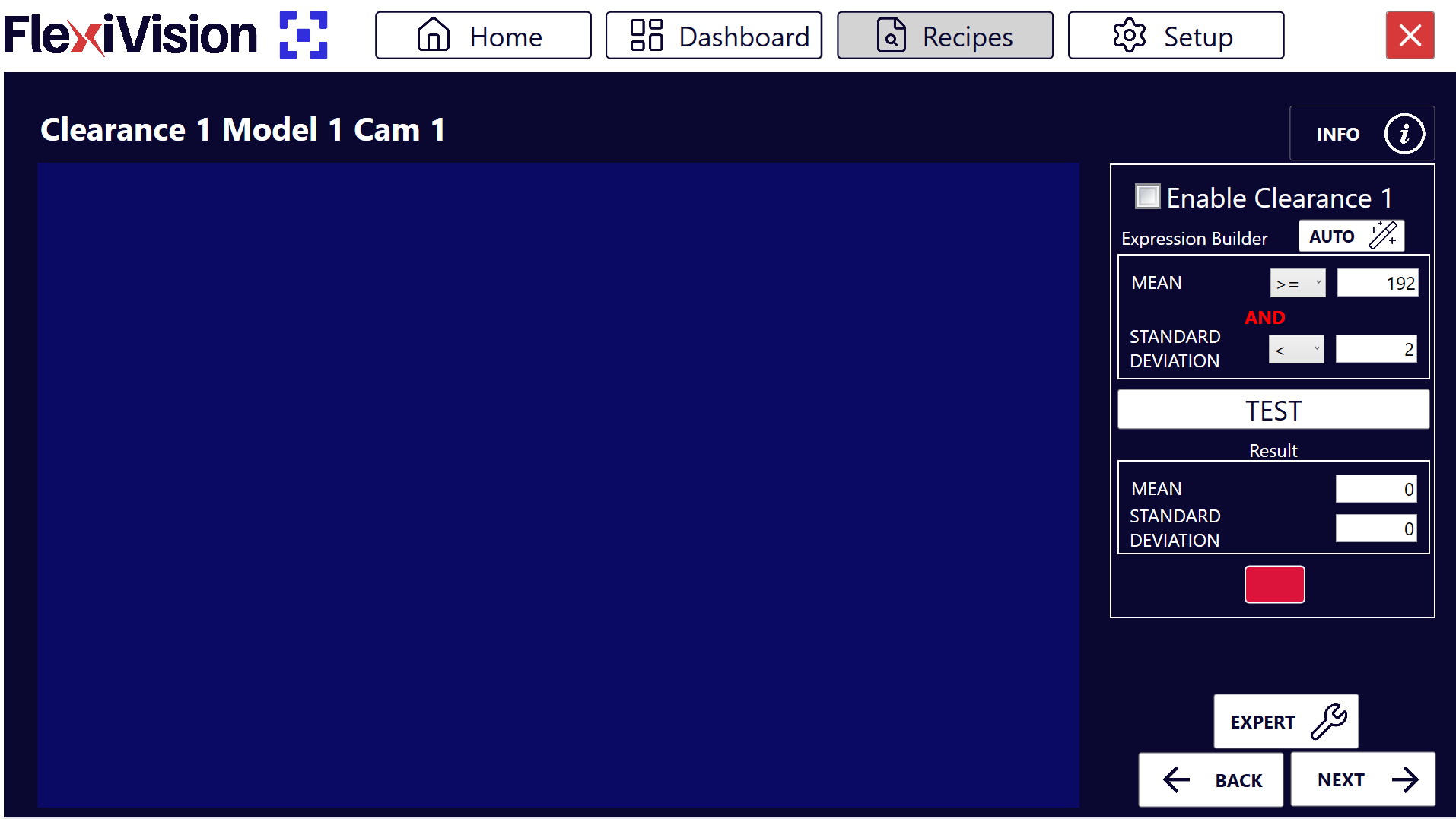
Click Clearance 1, the page for configuring the first clearance “Clearance 1” will open Clearance 1 Page
|
Step 3: Area Activation and Positioning#
8 |
Click Enable Clearance to activate the clearance |
9 |
Move the frame of the Clearance to the area that is to remain clear
Important Always keep these two important aspects in mind:
Failure to comply with these two points could lead to robot collisions resulting in damage to the FlexiBowl®, components or the robot itself. |
Tip
If you have any doubts during configuration, please consult the INFO key on the current page.
Step 4: Automatic Configuration#
10 |
Click |
11 |
Click |
12 |
Check that the box turns green |
13 |
Click |
 in Expression Builder
Warning
What to do if the test fails (red box)?
If after AUTO the box turns red:
Possible causes:
There is actually something in the area (part, shadow, dirt)
The lighting has changed between AUTO and TEST configuration
The selected area includes edges of the FlexiBowl® or artefacts
Solutions:
Visually check that the area is completely clear
Repeat AUTO with stable lighting conditions
Repeat TEST to verify
Tip
If you have any doubts during configuration, please consult the INFO key on the current page.
Multiple Clearances - When to Use Them#
Create more clearances when:
The robot tool is a gripper: a clearance is needed for each of the two areas engaged by the gripper on either side of the reference component
There are several critical points to monitor
The picking area has particular geometries
Step 2-3: Repetition#
Select a new clearance from the Clearance list page, such as “Clearance 2” and repeat Steps 2-3. Repeat the procedure for each clearance required (up to 8 per model).
Step 4: Overall Test#
On the list page of all clearances, click TEST to view all clearances at once
 #
#
Interpreting States#
Clearance States#
Colour |
Status |
Meaning |
Image |
|---|---|---|---|
🟢 Green |
OK |
Area clear, picking possible |
|
🔴 Red |
Triggered |
Area engaged, picking not possible |
|
What does “Triggered” mean?#
A clearance turns red (triggered) when it detects inside:
Presence of other components
Significant shadows or reflections
Any element that makes the area not clear
Step 5: Finalisation#
14 |
After configuring all necessary clearances, click |
15 |
The Robot Model Pick Cam page will open |
See also
Proceed to Robot Calibration to complete configuration.