3 FlexiBowl® and 3 Cameras#
This section describes the configurations available when you want to operate three FlexiBowl® devices and three cameras within the same picking cell, managed by a single FlexiVision One VisionController.
Configuration overview#
In a 3 FlexiBowl® + 3 camera configuration, the system comprises three independent feed and vision stations, all controlled by the same VisionController. Each station consists of:
1 FlexiBowl®
1 Camera with dedicated lens
1 Hopper (optional, if present)
The three stations communicate with the VisionController via a network switch.
Important
The Switch is a mandatory component in all multi-device configurations. Without it, it would not be possible to simultaneously connect several FlexiBowl® devices and several cameras to the VisionController. See the Switch section for technical specifications and order codes.
This configuration supports three operating variants, depending on the number of robots available in the system:
Variant A |
Variant B |
Variant C |
|
|---|---|---|---|
Robot |
1 |
2 |
3 |
FlexiBowl® |
3 |
3 |
3 |
Cameras |
3 |
3 |
3 |
Operational logic |
The robot reaches all three stations |
First robot on one FlexiBowl®, second robot on two FlexiBowl® |
Each robot is dedicated to a station |
Switch required |
Yes |
Yes |
Yes |
Variant A — 1 Robot, 3 FlexiBowl® devices#
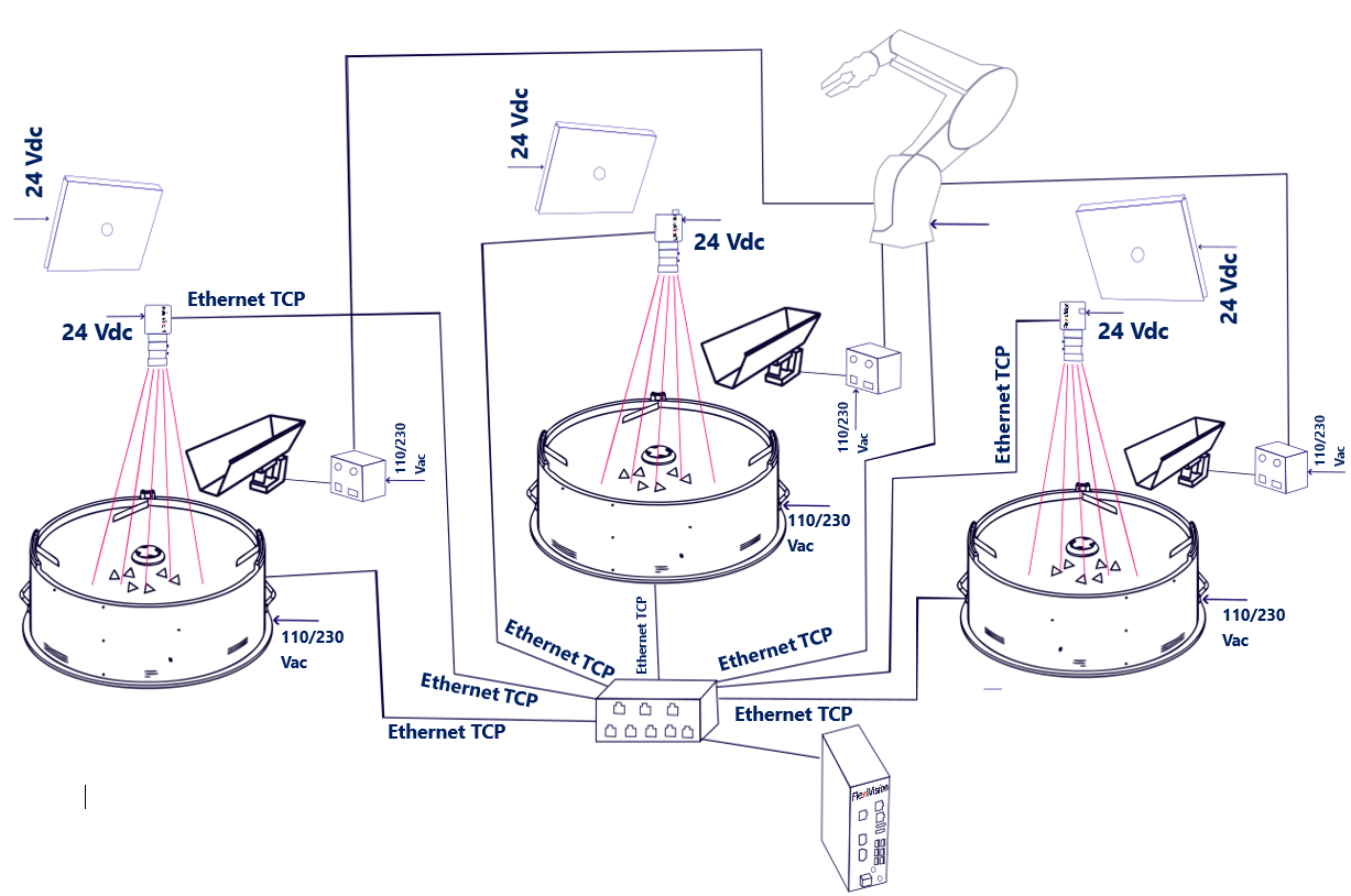
A single robot operates on all three stations. The robot must be positioned so that it can reach the picking area of each FlexiBowl®. The VisionController manages the three stations independently, each with its own recipe and TCP/IP communication channel.
Each station supports Standard or Mix applications.
Parameter |
Value |
|---|---|
FlexiBowl® |
3 |
Cameras |
3 |
Robot |
1 |
Switch required |
Yes |
Important
Basic recipe and recipe management
As with the single configuration, in a 3FB + 3CAM configuration, the process starts with the creation of a single basic recipe, which contains the hardware setup and camera calibration for the entire system. This basic recipe is then duplicated for each station: each duplicate constitutes the operating recipe for that station, within which the part models (up to 8 per station) are created.
Therefore, it is crucial that the pairing between the devices is configured correctly from the start:
Camera 1 → FlexiBowl® 1 (+ Hopper 1, if present)
Camera 2 → FlexiBowl® 2 (+ Hopper 2, if present)
Camera 3 → FlexiBowl® 3 (+ Hopper 3, if present)
An incorrect pairing during setup would affect all derived recipes, compromising the identification of parts and the correct operation of the entire system.
Variant B — 2 Robots, 3 FlexiBowl® devices#
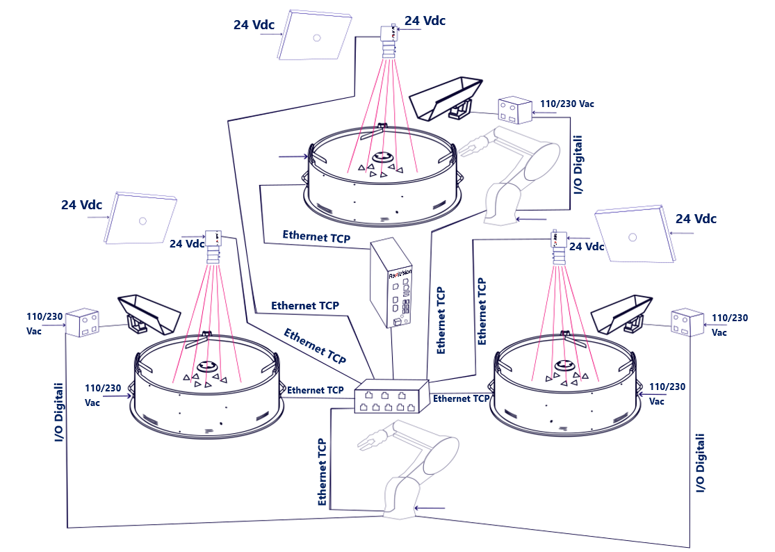
In this variant, two robots divide the three stations. The first robot will perform picking on only one FlexiBowl®, the second on the other two FlexiBowl® devices. The load distribution between robots is defined by the logic of the robot program and the physical layout of the system.
Each station supports Standard or Mix applications.
Parameter |
Value |
|---|---|
FlexiBowl® |
3 |
Cameras |
3 |
Robot |
2 |
Switch required |
Yes |
Important
Basic recipe and recipe management
As with the single configuration, in a 3FB + 3CAM configuration, the process starts with the creation of a single basic recipe, which contains the hardware setup and camera calibration for the entire system. This basic recipe is then duplicated for each station: each duplicate constitutes the operating recipe for that station, within which the part models (up to 8 per station) are created.
Therefore, it is crucial that the pairing between the devices is configured correctly from the start:
Camera 1 → FlexiBowl® 1 (+ Hopper 1, if present)
Camera 2 → FlexiBowl® 2 (+ Hopper 2, if present)
Camera 3 → FlexiBowl® 3 (+ Hopper 3, if present)
An incorrect pairing during setup would affect all derived recipes, compromising the identification of parts and the correct operation of the entire system.
Variant C — 3 Robots, 3 FlexiBowl® devices#
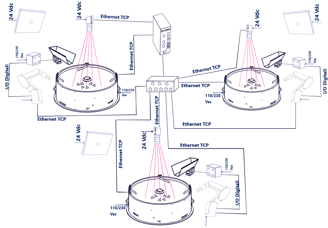
Each robot is dedicated to a single station: maximum productivity with the three cells operating in parallel and completely independently.
Each station supports Standard or Mix applications.
Parameter |
Value |
|---|---|
FlexiBowl® |
3 |
Cameras |
3 |
Robot |
3 |
Switch required |
Yes |
Tip
The C variant guarantees the best overall performance. Each cell is completely autonomous and does not depend on the availability of the others.
Important
Basic recipe and recipe management
As with the single configuration, in a 3FB + 3CAM configuration, the process starts with the creation of a single basic recipe, which contains the hardware setup and camera calibration for the entire system. This basic recipe is then duplicated for each station: each duplicate constitutes the operating recipe for that station, within which the part models (up to 8 per station) are created.
Therefore, it is crucial that the pairing between the devices is configured correctly from the start:
Camera 1 → FlexiBowl® 1 (+ Hopper 1, if present)
Camera 2 → FlexiBowl® 2 (+ Hopper 2, if present)
Camera 3 → FlexiBowl® 3 (+ Hopper 3, if present)
An incorrect pairing during setup would affect all derived recipes, compromising the identification of parts and the correct operation of the entire system.
Necessary components#
FlexiVision One basic kit#
The FlexiVision One basic kit (supplied with the system) already includes everything needed for the first station (camera, lens, cables, calibration grid), including the VisionController. There is no need to purchase a second complete kit for additional stations.
Additional Camera Kit (× 2)#
For stations 2 and 3, two Additional Camera Kits must be purchased, one for each station, by selecting the code corresponding to the size of the FlexiBowl® of each station. The kit includes:
1 Camera
1 specific lens for that FlexiBowl® size
1 Calibration grid
1 Camera power cable
2 Ethernet cables
Select the kit according to the size of the FlexiBowl® of each additional station:
FlexiBowl® size |
Additional Camera Kit Code |
Lens included |
|---|---|---|
FB 200 |
GM002002 |
CE000881 — FlexiVision One 35mm Optic |
FB 350 |
GM002003 |
CE000881 — FlexiVision One 35mm Optic |
FB 500 |
GM002004 |
CE000880 — FlexiVision One 25mm Optic |
FB 650 |
GM002005 |
CE000879 — FlexiVision One 16mm Optic |
FB 800 |
GM002006 |
CE000879 — FlexiVision One 16mm Optic |
FB 1200 |
GM002007 |
CE000878 — FlexiVision One 12mm Optic |
Note
If your additional stations use different sized FlexiBowl® devices, purchase one kit for each size.
For example, for a configuration with FB500 + FB650 + FB800, the basic kit covers the first station, while for the second and third stations you need to order GM002004 and GM002006 respectively.
Switch#
The Switch is always required in multi-device configurations. For code, electrical and physical specifications, see the dedicated section:
→ Switch
Wiring#
In Variant A (1 robot), all field devices (FlexiBowl®, cameras, robot) connect to the Switch, and the Switch connects to the VisionController via a single Ethernet port. The total number of connections fits the 8 ports available on the Switch.
From Variant B onwards, the total number of devices exceeds the ports available on the Switch.
In these cases, one port of the VisionController is used to connect it to the Switch, while the remaining free ports of the VisionController accommodate devices that do not fit on the Switch:
In Variant B (2 robots), the FlexiBowl® 3 connects directly to a free VisionController port.
In Variant C (3 robots), the FlexiBowl® 3 and Camera 3 connect directly to the free ports of the VisionController.
Important
The Switch has 8 Ethernet ports. Starting with Variant B, it is not possible to connect all devices exclusively via the Switch: extra devices must be connected directly to the free Ethernet ports on the VisionController, as shown in the tables below.
Note
You can arbitrarily decide which devices to connect to the VisionController. You must always leave a free port to connect the VisionController to the Switch.
Connection diagram#
Device |
Variant A (1 Robot) |
Variant B (2 Robots) |
Variant C (3 Robots) |
|---|---|---|---|
FlexiBowl® 1 |
→ Switch |
→ Switch |
→ Switch |
FlexiBowl® 2 |
→ Switch |
→ Switch |
→ Switch |
FlexiBowl® 3 |
→ Switch |
→ VisionController (free port) |
→ VisionController (free port) |
Camera 1 |
→ Switch |
→ Switch |
→ Switch |
Camera 2 |
→ Switch |
→ Switch |
→ Switch |
Camera 3 |
→ Switch |
→ Switch |
→ VisionController (free port) |
Robot 1 |
→ Switch |
→ Switch |
→ Switch |
Robot 2 |
— |
→ Switch |
→ Switch |
Robot 3 |
— |
— |
→ Switch |
Switch |
→ VisionController |
→ VisionController |
→ VisionController |
Note
You can arbitrarily decide which devices to connect to the VisionController. You must always leave a free port to connect the VisionController to the Switch.
Tip
Make sure each device is assigned a unique IP address in the same subnet.
The TCP/IP ports used by the VisionController for the three stations are configurable: by default FB1 → 4001, FB2 → 4002, FB3 → 4003.
Refer to the Robot-Vision Communication Protocol section for details.
Switch ports engaged per variant#
Switch Port |
Variant A (1 Robot) |
Variant B (2 Robots) |
Variant C (3 Robots) |
|---|---|---|---|
1 |
FlexiBowl® 1 |
FlexiBowl® 1 |
FlexiBowl® 1 |
2 |
FlexiBowl® 2 |
FlexiBowl® 2 |
FlexiBowl® 2 |
3 |
FlexiBowl® 3 |
Camera 1 |
Camera 1 |
4 |
Camera 1 |
Camera 2 |
Camera 2 |
5 |
Camera 2 |
Camera 3 |
Robot 1 |
6 |
Camera 3 |
Robot 1 |
Robot 2 |
7 |
Robot 1 |
Robot 2 |
Robot 3 |
8 |
VisionController |
VisionController |
VisionController |
VisionController ports engaged per variant#
VisionController port |
Variant A (1 Robot) |
Variant B (2 Robots) |
Variant C (3 Robots) |
|---|---|---|---|
1 |
Switch |
Switch |
Switch |
2 |
— |
FlexiBowl® 3 |
FlexiBowl® 3 |
3 |
— |
— |
Camera 3 |
Note
You can arbitrarily decide which devices to connect to the VisionController. You must always leave a free port to connect the VisionController to the Switch.
Note
In Variant B the Switch ports are all engaged (7 devices + VisionController): the FlexiBowl® 2 connects directly to the VisionController. In Variant C Camera 3 also connects directly to the VisionController, engaging the third available port.
Note
Wiring of individual components
The physical connection procedures of each component (FlexiBowl®, camera, hopper, robot) are fully described in the Wiring and Connections section.
In a 3FB + 3CAM configuration, the same operations simply have to be performed three times — once for each station — with the only difference being that each device connects to the Switch rather than directly to the VisionController, with the exception of FlexiBowl® 2 (Variants B and C) and Camera 3 (Variant C), which connect directly to the VisionController’s free Ethernet ports.
Important
Device pairing in software
FlexiVision One can manage all stations simultaneously, but it is essential that device pairing be configured correctly in the software. Make sure to pair:
Camera 1 → FlexiBowl® 1 (+ Hopper 1, if present)
Camera 2 → FlexiBowl® 2 (+ Hopper 2, if present)
Camera 3 → FlexiBowl® 3 (+ Hopper 3, if present)
An incorrect pairing would compromise the tracking of the parts and the proper operation of the entire system.
→ Initial System Configuration