Camera and Robot Calibration#
Calibration is the crucial step that establishes the exact geometric relationship between the real world (coordinates in millimetres) and the image captured by the camera (pixels). Without accurate calibration, the precision of the picking system is compromised, making the entire application unreliable.
Tip
It is not necessary to re-calibrate if the position of the FlexiBowl® is altered.
Why is calibration necessary?#
Calibration is necessary because each combination of sensor and lens introduces specific alterations to the image. Its main goal is to correct these distortions.
Types of optical distortions#
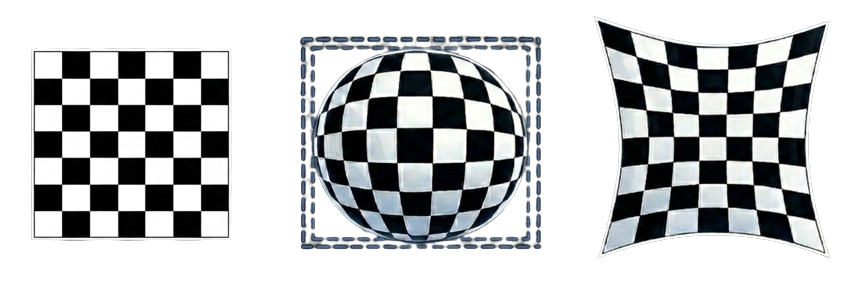
Examples of optical distortions: no distortion (left), barrel distortion (centre), pincushion distortion (right)#
Step 1: Calibration grid#
Error
Make sure to have:
Backlight on (SETUP > FlexiBowl® Setup > Config FlexiBowl® > Light ON active)
Toplight off
The dedicated ARS calibration grid must be placed on the FlexiBowl®:
Step |
Operation |
Image |
|---|---|---|
0 |
If present, remove any diverters mounted on the FlexiBowl®. |
|
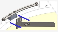
1 |
Loosen the four screws of the FlexiBowl® central flange. |
|
2 |
Turn the central flange slightly anti-clockwise and remove it. |
|
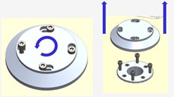
3 |
Lift the surface carefully and remove it. |
|
4 |
If necessary, apply magnetic spacers to the four sides of the grid. |
|
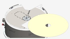
5 |
Position the ARS grid on the FlexiBowl® by aligning the positioning pins with the predefined holes on the edge of the backlight. |
|
Correct positioning of the ARS calibration grid on the FlexiBowl®#
Attention
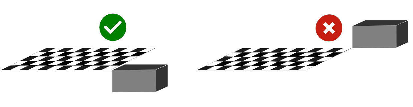
The calibration grid must be positioned at the same height as the object used in the application.
For this reason, it is supplied with spacers to be inserted into the grid pegs before installing it on the FlexiBowl®.
The spacers raise the grid to the level of the part height, ensuring accurate calibration.
Step 2: Fundamental adjustments#
5 |
Access the Camera SETUP section from the SETUP section |
6 |
Click the Config Camera button of the corresponding camera |
7 |
Click EXPERT on the Camera FLB page |
8 |
Put the camera in live display mode Before adjusting the aperture, activate the continuous view mode: 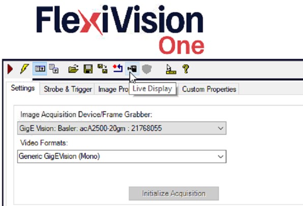
|
9 |
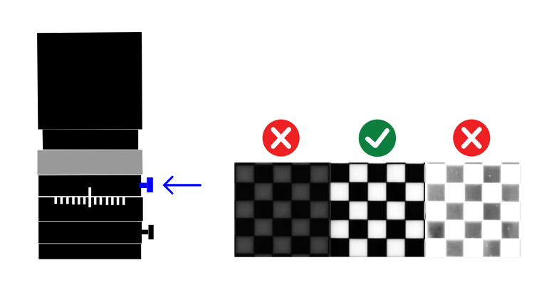
Set the aperture
|
10 |
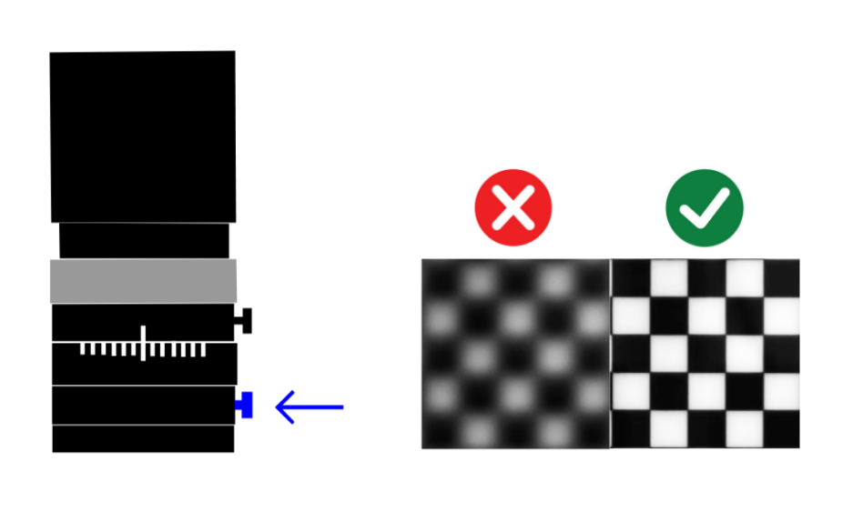
Manually adjust the focus of the camera
|
11 |
Click Back |
Warning
Attention to depth of field
Focusing should ensure sharpness over the entire surface of the FlexiBowl®, not just in the centre.
If the centre is sharp but the edges are blurred:
Check that the lens is clean
Check that the working distance is correct
Check that the camera is perfectly parallel to the working surface of the FlexiBowl®
Close the aperture slightly to increase the depth of field
If the problem persists, the mechanical assembly of the camera may need to be reviewed.
Error
If clicking the RUN button several times produces a completely blue screen even once, refer to Troubleshooting Camera Setup
12 |
Adjust camera exposure
|
13 |
Click NEXT |
 , repeat this step until the correct exposure for the image is found:
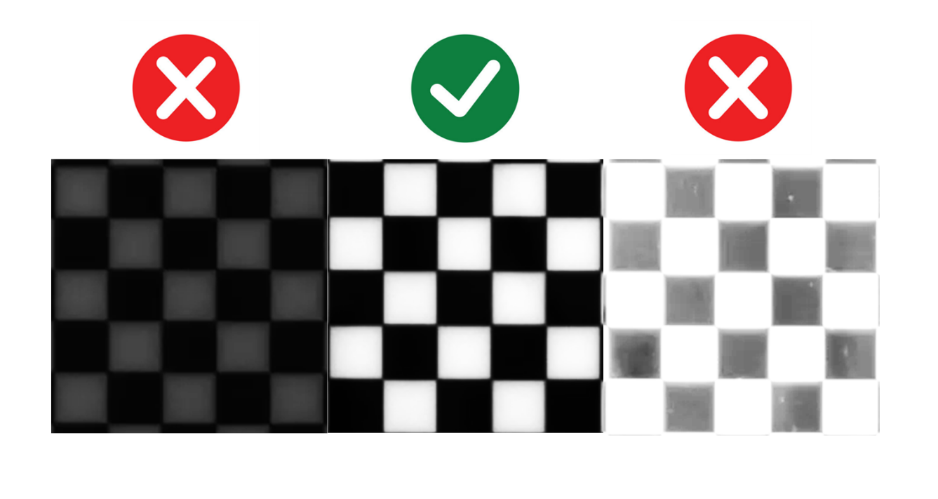
Example of correct exposure: high contrast, well-defined pattern, no burnt areas#
Tip
Exposure optimisation
The longer the time, the more light will enter the lens
Time too short: Dark image, poorly visible pattern
Time too long: Overexposed image, loss of detail
Optimum time: Maximum contrast without saturation
Tip
If you have any doubts during configuration, please consult the INFO key on the current page.
Step 3: Camera Calibration#
14 |
Check that the grid is centred, sharp and fully visible before capturing the calibration image. |
15 |
Click ‘Grab Image’ to take a picture of the calibration grid. Visually verify that:
|
16 |
Set ‘Tile Size X’ and ‘Tile Size Y’ both to 10 for all FlexiBowl® 500 to 1200 models. |
17 |
Click ‘Calibrate’ to carry out calibration |
18 |
Assessing the quality of calibration The ‘Result Calibration’ parameter will return a value: 🟢 Excellent (Green): Excellent calibration, optimal accuracy. 🟠 Acceptable (Orange): Acceptable calibration, good but not optimal accuracy. 🔴 Bad (Red): Poor calibration, insufficient accuracy. Must be repeated. Important Accept only Excellent 🟢 calibrations; other results will compromise the operation of the entire application. |
Note
Acceptance criterion
A satisfactory result includes setting the aperture, focusing, and setting the best exposure for the application.
Warning
Errors during calculation
If the calibration calculation fails:
Possible causes:
Pattern not detected (image too dark or overexposed)
Grid squares partially obscured
Excessive distortion (camera too close or far away)
Incorrect Tile Size entered
Solution:
Check and improve the quality of the captured image
Make sure the entire grid is visible and well lit
Check the Tile Size value
Repeat Grab Image and try again
Tip
If you have any doubts during configuration, please consult the INFO key on the current page.
When calibration needs to be repeated#
Recalibrate when: |
First system setup (mandatory). After changing the position of the camera. After moving the robot. If there are systematic picking errors. |
It is not necessary to recalibrate when: |
If you change the type of part for the same FlexiBowl® and camera. If you change focus or lens aperture. If you change the software recipe. If you adjust identification parameters. If you update the robot programs. |
Robot Calibration#
Step 4: Laser Mounting#
19 |
Once an excellent-quality calibration is obtained, click A window will appear requesting robot calibration before continuing; DO NOT click “Yes” and follow the next steps |
20 |
Mount the Laser Tool with its custom bracket Important The bracket for mounting the Laser Tool in place of the robot tool is NOT supplied, as it varies for each robot and must be customised. 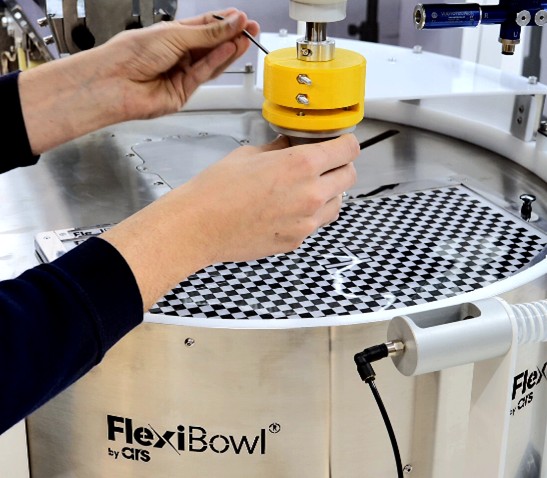
|
21 |
Position the Spacer Bracket (A) under the laser 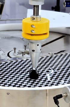
|
22 |
Lower the laser to the spacer level (A), so the laser is exactly 3 cm above the calibration grid 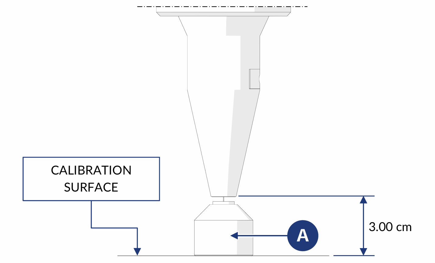
|
23 |
Remove the Spacer Bracket 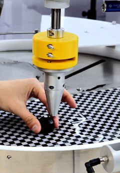
|
24 |
Turn on the laser 
|
 .
.Tip
If you have any doubts during configuration, please consult the INFO key on the current page.
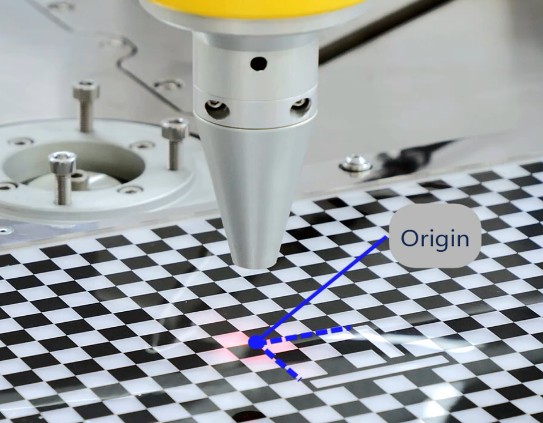
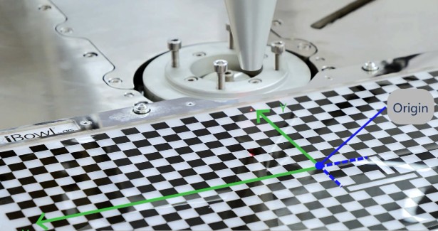
Step 5: Drawing a 3-point plane#
25 |
Bring the laser to the origin point |
|
26 |
Bring the laser to the end point of the X axis |
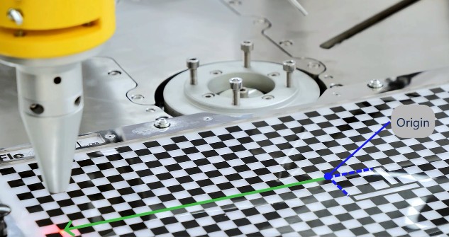
|
27 |
Bring the laser to the end point of the Y axis |
|
Tip
If you have any doubts during configuration, please consult the INFO key on the current page.
Step 6: Checking robot trajectory#
28 |
Return the laser to the origin point |
29 |
Move the robot from its teach pendant along the X and Y axes. |
30 |
Verify that the correct trajectory is followed: the robot, moving exclusively along the X and Y axes, must correctly follow the grid lines |
31 |
Click “YES” 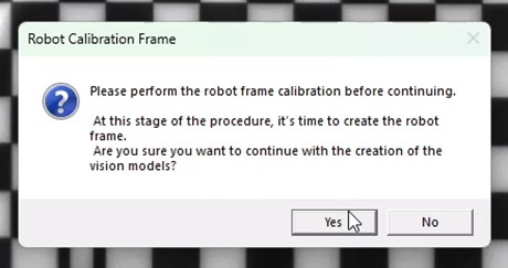
|
Tip
If you have any doubts during configuration, please consult the INFO key on the current page.
Step 7: Saving Basic Recipe#
32 |
Click |
33 |
Check that you have the recipe containing all setups and calibration selected in the menu on the left and click |
34 |
This will allow you to have all the steps taken so far saved separately, so as to have a basis for all future recipes containing the various models for the calibrated system |
35 |
To continue with model creation, duplicate the basic recipe, rename it as you prefer and click |


 : a page will open with a list of all available models
Common problems during calibration#
Pattern not detected#
Warning
Error: “Unable to detect calibration pattern”
Cause: The software cannot identify the grid pattern.
Solutions:
Increase contrast (adjust exposure or lighting)
Check that the entire grid is visible in the image
Improve focus
Clean the surface of the grid (dust or fingerprints may interfere)
Calibration always “Bad” or “Acceptable”#
Warning
Insufficient calibration quality
If, despite adjustments, calibration remains less than ‘Excellent’:
Check the camera-FlexiBowl® working distance (it must be as calculated)
Check that the camera is parallel to the plane of the FlexiBowl® (it must be perfectly horizontal)
Make sure the camera is stable (no vibrations while capturing)
Check that the lens is screwed in all the way
If the problem persists, there may be a mechanical problem in the assembly. Consult Mechanical Installation for review.
Next steps#
Once the Camera and Robot calibrations have been completed, proceed with: