FlexiVision One Detailed Specifications#
This section provides full technical specifications of the FlexiVision One system, including details of the industrial camera, VisionController, calibration grid, communication protocols and hardware configurations.
Camera#
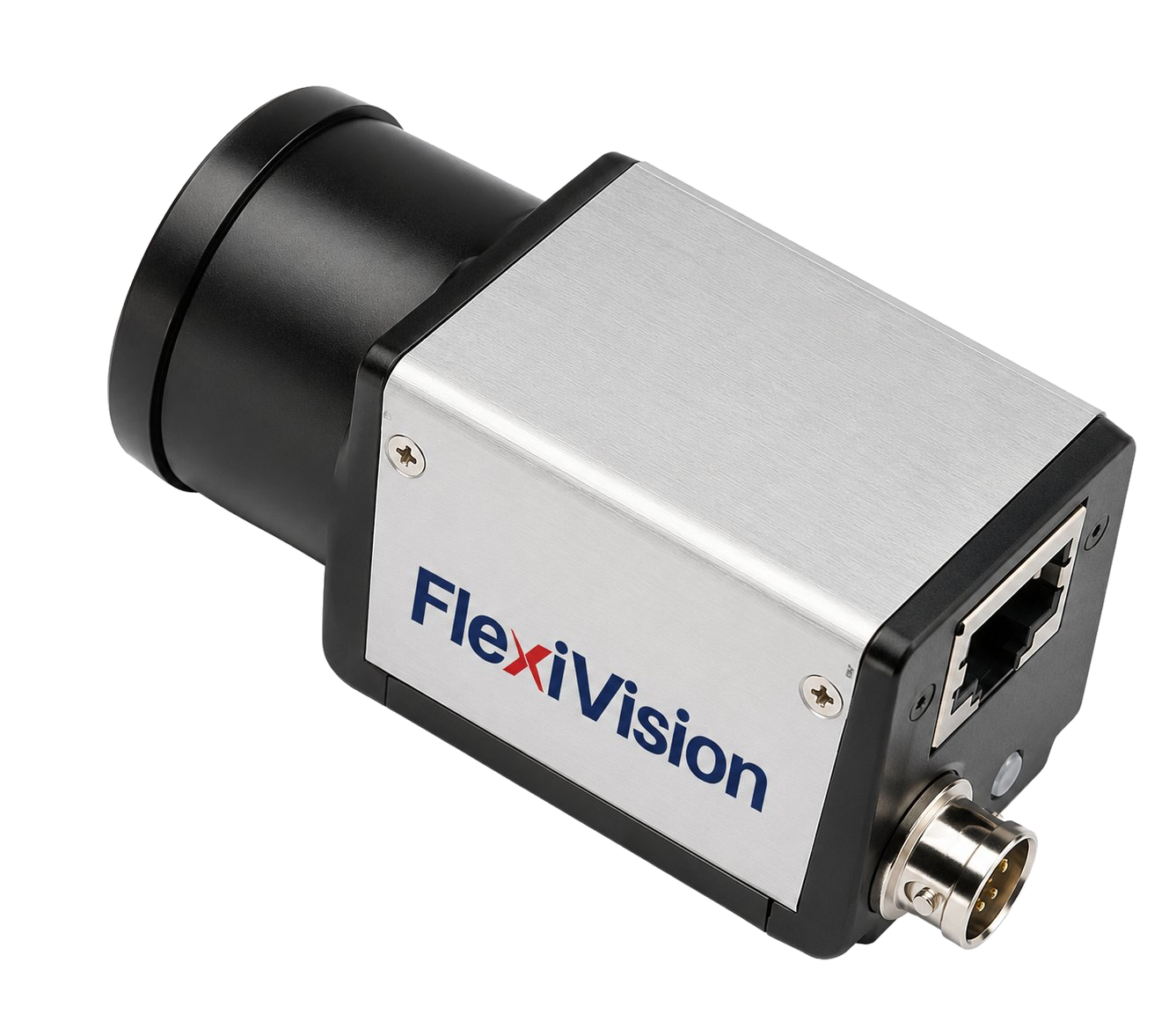
The FlexiVision One system uses high-resolution cameras with a Gigabit Ethernet interface for fast image acquisition and accurate component identification.
Electrical specifications#
Feature |
Specifications |
|---|---|
Model |
CAM-CIC-5000-20G-1 |
Effective Pixels |
5 MP 12448 × 2048 |
SNR |
>38 dB |
Dynamic Range |
70 dB |
GPIO |
Hirose 6-pin connector: 1 opto-isolated input, 1 opto-isolated output, 1 configurable I/O without optical isolation |
Image Format |
Mono8 / 10 / 10Packed |
Binning |
Support |
Gain |
X1 ~ X32 |
Gamma |
0 to 4, LUT support |
Exposure Time |
34.23 μS ~ 1S |
Trigger Mode |
Software / Hardware / Free run |
Image Buffer |
256 MB |
user settings |
Support two sets of user-defined configuration |
Power Supply |
PoE / DC via Hirose connector, with 12 V or 24 V voltage |
Power Consumption |
12V ≈ 3.2 W |
Lens Mount |
C-mount |
Operating Temperature |
-30°C ~ +50°C |
Storage Temperature |
-30°C ~ +80°C |
Certifications |
CE, UL, FCC, RoHS |
Resolution |
2448 x 2048 |
Pixel Size |
3.45 × 3.45 μm |
Sensor |
IMX264 CMOS Global Shutter |
Sensor Size |
2/3” |
Frame Rate |
24 fps |
Bit Depth |
12 bit |
Interface |
GigE, POE |
GPIO connector (Hirose 6-pin)#
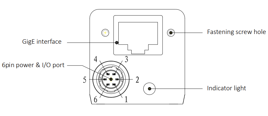
Rear view of the camera with connectors#
Warning
Mandatory network requirements
The Gigabit Ethernet interface is mandatory and requires a compatible Gigabit Ethernet network infrastructure and Ethernet cables of at least Cat6 or Cat7 category with S/STP shielding.
Failure to comply with this requirement completely jeopardises the camera’s operation. Check that all network components (cables, switches, ports) support the GigE standard.
Power supply methods#
Tip
Which method should be chosen?
PoE: ideal for clean installations with only one cable, but requires specific network hardware
External power supply: more flexible standard solution, recommended for most applications
Power cable#
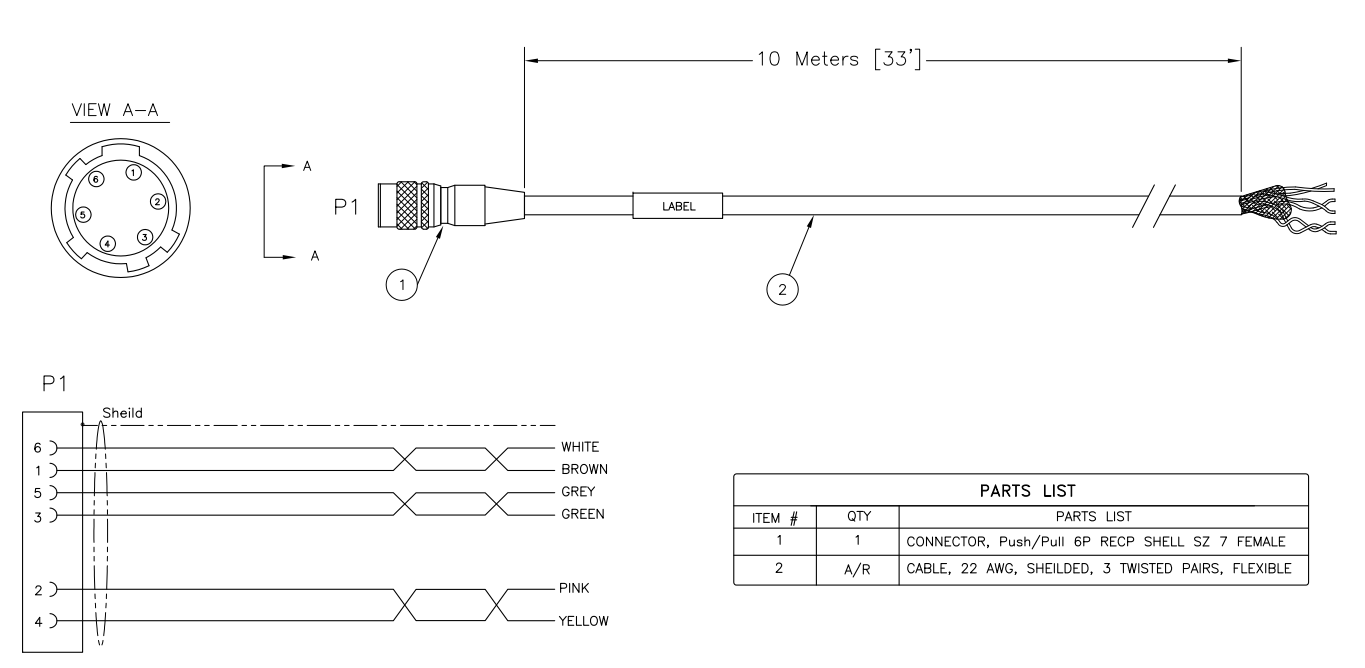
Camera Power Cable Specifications#
Parameter |
Value |
|---|---|
Description |
I/O 10-metre cable, HRS6P connector |
Compatibility |
CIC-series cameras |
Length |
10 metres 133’ |
Connector 1P1 |
Push/Pull 6P RECP Shell SZ 7 Female |
Conductor cross-section |
22 AWG |
Cable type |
Shielded, 3 twisted pairs, flexible |
Cable colours |
Pin 1: Brown, Pin 2: Green , Pin 3: Pink, Pin 4: Yellow, Pin 5: Grey, Pin 6: White |
Shielding |
Shield on all conductors |
Compliance |
UL/CSA and RoHS |
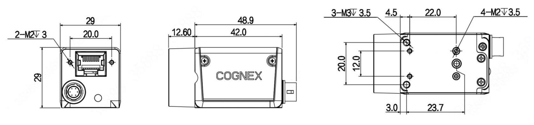
Physical specifications and dimensions#
Feature |
Value |
|---|---|
Width × Height (body) |
29 × 29 mm |
Depth (body) |
42.0 mm |
Total depth (including rear connector) |
48.9 mm |
Front projection (lens mount) |
12.60 mm |
Side fixing holes centre distance (M2) |
20.0 × 23.7 mm |
Front fixing holes |
2× M2 depth 3 mm |
Side fixing holes |
4× M2 depth 3.5 mm + 3× M3 depth 3.5 mm |
Weight |
88 g |
Lens#
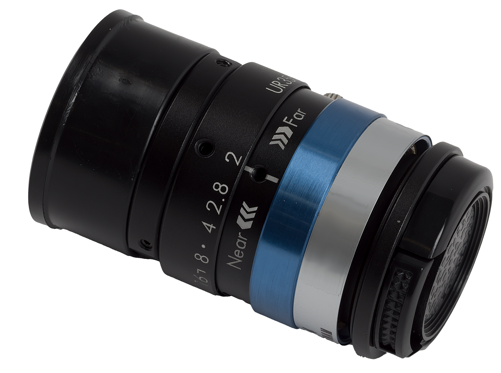
35mm Lens
Parameter |
Reference Magnification |
M.O.D. |
|---|---|---|
Lens type |
CCTV Lens |
CCTV Lens |
Focus position |
Reference Magnification |
M.O.D. |
Magnification |
0.069 |
0.167 |
Focal length (mm) |
34.97 |
34.97 |
F-Number (Fno) |
2.00 ~ 16.00 |
2.00 ~ 16.00 |
Numerical Aperture (NA) |
- |
- |
Working distance / object (mm) |
500.0 / 507.0 |
200.0 / 207.0 |
Object-image distance (mm) |
555.75 |
259.16 |
Mechanical length of tube (mm) |
36.30 ~ 38.20 |
36.30 ~ 38.20 |
Lens back focus (mm) |
14.75 |
18.16 |
Depth of field (mm) |
35.476 |
6.336 |
Resolution @550nm (µm) |
- |
- |
Main plane position front/rear (mm) |
37.60 / -22.61 |
37.60 / -22.61 |
Entr./Exit pupil position (mm) |
25.22 / -41.78 |
25.22 / -41.78 |
Entr./Exit pupil diameter (mm) |
17.03 / 26.36 |
17.03 / 26.36 |
Angle of view ° H × V |
13.69 × 10.34 |
12.62 × 9.76 |
TV distortion % |
-0.088 |
-0.142 |
Relative illumination % |
44.95 |
50.20 |
Weight (g) |
50 |
50 |
Mount |
C-mount |
C-mount |
Image circle (mm) |
φ11 |
φ11 |
Maximum compatible camera |
2/3” |
2/3” |
Lens 25mm
Parameter |
Reference Magnification |
M.O.D. |
|---|---|---|
Lens type |
CCTV Lens |
CCTV Lens |
Focus position |
Reference Magnification |
M.O.D. |
Magnification |
0.049 |
0.152 |
Focal length (mm) |
25.00 |
25.00 |
F-number (Fno) |
1.60 ~ 16.00 |
1.60 ~ 16.00 |
Numerical aperture (NA) |
- |
- |
Working distance / object (mm) |
500.0 / 510.0 |
150.0 / 160.0 |
Object-image distance (mm) |
553.34 |
205.92 |
Mechanical length of tube (mm) |
34.60 ~ 38.50 |
34.60 ~ 38.50 |
Lens back focus (mm) |
13.75 |
16.33 |
Depth of field @PCoC 0.04mm (mm) |
54.223 |
5.835 |
Resolution @550nm (µm) |
- |
- |
Main plane position front/rear (mm) |
29.42 / -12.46 |
29.42 / -12.46 |
Entr./Exit pupil position (mm) |
18.48 / -31.94 |
18.48 / -31.94 |
Entr./Exit pupil diameter (mm) |
15.92 / 28.32 |
15.92 / 28.32 |
Angle of view ° H × V |
19.39 × 14.64 |
18.05 × 13.89 |
TV distortion % |
-0.041 |
-0.271 |
Relative illumination % |
49.78 |
53.52 |
Weight (g) |
50 |
50 |
Mount |
C-mount |
C-mount |
Image circle (mm) |
φ11 |
φ11 |
Maximum compatible camera |
2/3” |
2/3” |
Lens 16mm
Parameter |
Reference Magnification |
M.O.D. |
|---|---|---|
Lens type |
CCTV Lens |
CCTV Lens |
Focus position |
Reference Magnification |
M.O.D. |
Magnification |
0.031 |
0.095 |
Focal length (mm) |
16.16 |
16.16 |
F-number (Fno) |
1.60 ~ 16.00 |
1.60 ~ 16.00 |
Numerical aperture (NA) |
- |
- |
Working distance / object (mm) |
500.0 / 507.0 |
150.0 / 157.0 |
Object-image distance (mm) |
554.26 |
205.30 |
Mechanical length of tube (mm) |
35.50 ~ 37.00 |
35.50 ~ 37.00 |
Lens back focus (mm) |
12.16 |
13.20 |
Depth of field @PCoC 0.04mm (mm) |
131.893 |
14.387 |
Resolution @550nm (µm) |
- |
- |
Main plane position front/rear (mm) |
28.44 / -4.50 |
28.44 / -4.50 |
Entr./Exit pupil position (mm) |
18.85 / -28.07 |
18.85 / -28.07 |
Entr./Exit pupil diameter (mm) |
10.18 / 25.02 |
10.18 / 25.02 |
Angle of view ° H × V |
30.37 × 22.92 |
29.62 × 22.39 |
TV distortion % |
-0.472 |
-0.674 |
Relative illumination % |
32.75 |
36.61 |
Weight (g) |
50 |
50 |
Mount |
C-mount |
C-mount |
Image circle (mm) |
φ11 |
φ11 |
Maximum compatible camera |
2/3” |
2/3” |
Lens 12mm
Parameter |
Reference Magnification |
M.O.D. |
|---|---|---|
Lens type |
CCTV Lens |
CCTV Lens |
Focus position |
Reference Magnification |
M.O.D. |
Magnification |
0.023 |
0.075 |
Focal length (mm) |
12.00 |
12.00 |
F-number (Fno) |
1.80 ~ 16.00 |
1.80 ~ 16.00 |
Numerical aperture (NA) |
- |
- |
Working distance / object (mm) |
500.0 / 505.6 |
150.0 / 155.0 |
Object-image distance (mm) |
559.55 |
209.55 |
Mechanical length of tube (mm) |
39.20 ~ 40.10 |
39.20 ~ 40.10 |
Lens back focus (mm) |
12.23 |
12.84 |
Depth of field @PCoC 0.04mm (mm) |
277.576 |
28.121 |
Resolution @550nm (µm) |
- |
- |
Main plane position front/rear (mm) |
17.71 / -0.05 |
17.71 / -0.05 |
Entr./Exit pupil position (mm) |
11.68 / -12.18 |
11.68 / -12.18 |
Entr./Exit pupil diameter (mm) |
6.67 / 13.41 |
6.67 / 13.41 |
Angle of view ° H × V |
40.54 × 30.77 |
39.40 × 30.05 |
TV distortion % |
-0.983 |
-0.905 |
Relative illumination % |
40.64 |
42.64 |
Weight (g) |
60 |
60 |
Mount |
C-mount |
C-mount |
Image circle (mm) |
φ11 |
φ11 |
Maximum compatible camera |
2/3” |
2/3” |
VisionController#
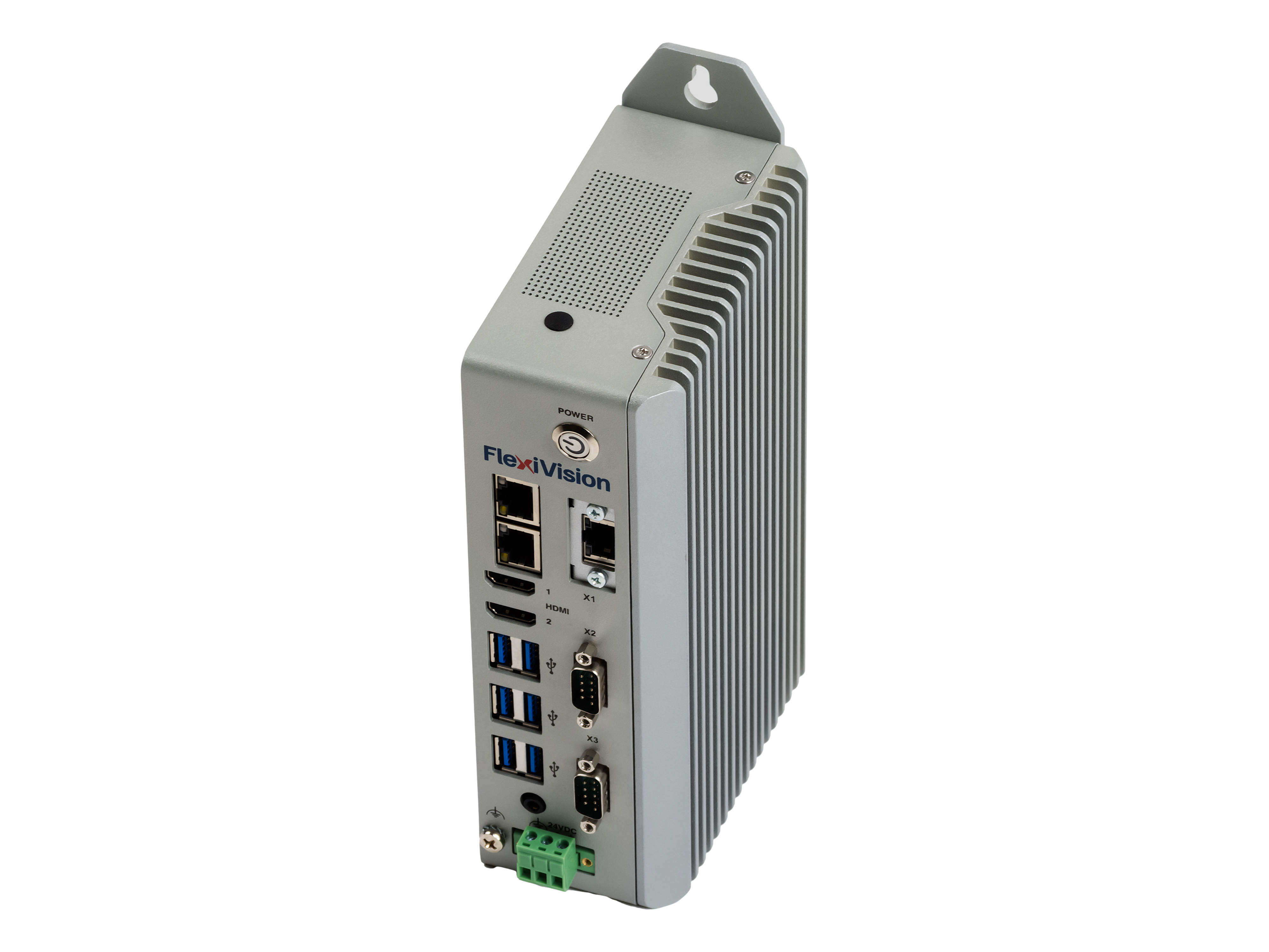
The FlexiVision One system operates on an Industrial PC (VisionController) that serves as the main controller for the vision software. ARS supplies the VisionController already pre-configured and tested with the FlexiVision One software installed.
Electrical specifications#
Feature |
Specifications |
|---|---|
CPU |
Intel Core i3-1115G4 1.7 14.1 GHz |
Memory (RAM) |
8G DDR4 3200 MHz |
Storage |
256G |
TPM |
TPM 2.0 |
Operating system |
Win11 LTSC 2024 |
Power button |
Yes (front panel with indicator light) |
Ethernet ports |
i3/i7: 3× Gb LAN |
USB Ports |
6× USB 3.0 TypeA |
Video Output |
2× HDMI |
Audio |
Line Out + MIC (2-in-1 jack) |
Power Supply (V DC) |
12 ~ 32 V DC |
Operating Temperature |
1°C ~ +50°C |
Storage Temperature |
-20°C ~ +65°C |
Humidity |
<90% (non-condensing) |
Body Material |
Aluminium alloy + steel |
Degree of Protection |
IP20 |
Installation Method |
Wall Mounting (DIN Rail optional) |
Power Consumption |
25 W |
Dimensions (W × H × D) |
59.8 × 200 × 119.5 mm |
Weight |
2 kg |
Certifications |
CE, UL |
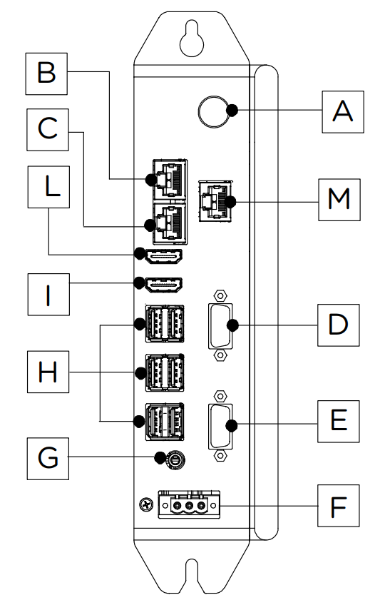
PC ports#
Physical specifications#
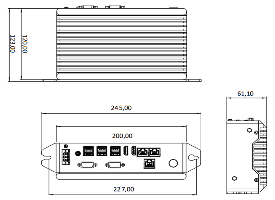
Screw holes |
M5 |
|---|---|
Feature |
Value |
Width (total with brackets) |
245.00 mm |
Width (body) |
227.00 mm |
Connector panel width |
200.00 mm |
Height (total with brackets) |
123.00 mm |
Body height |
120.00 mm |
Depth |
61.10 mm |
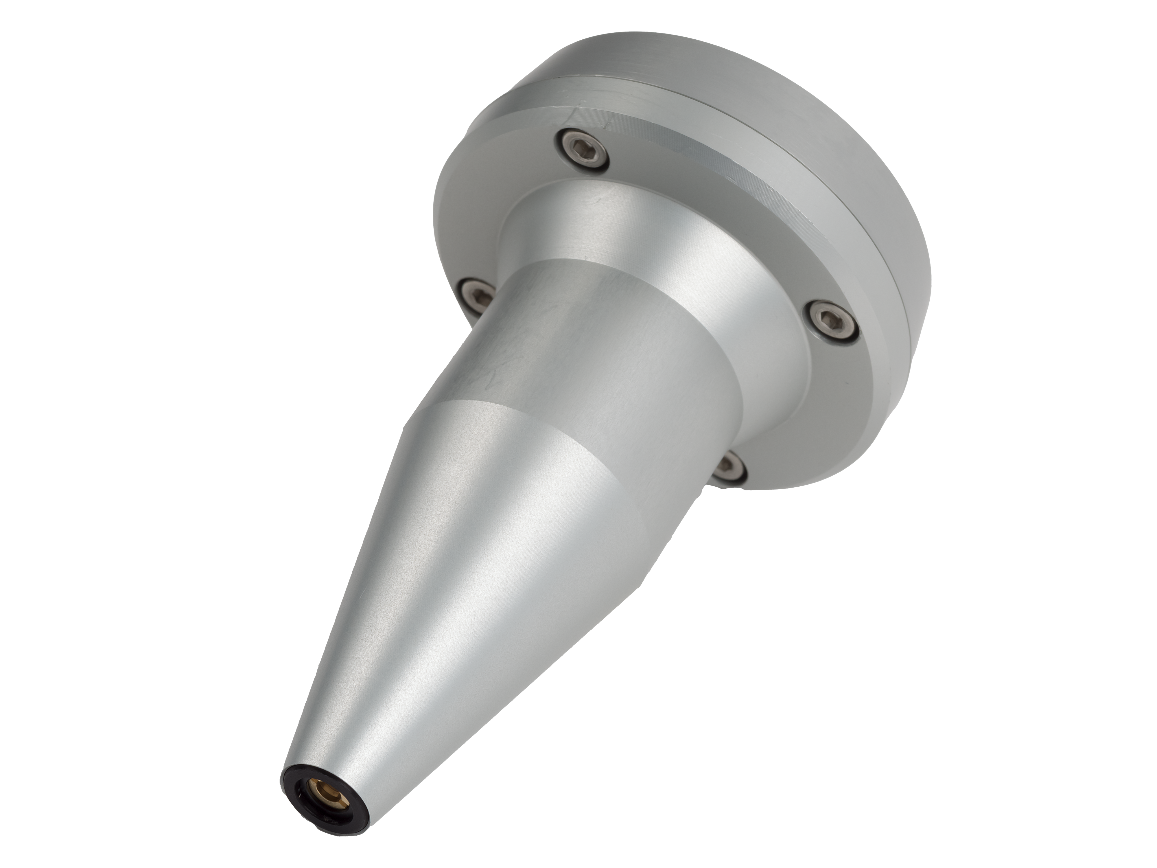
Laser Tool for Calibration#
The Laser Tool is an advanced calibration solution that improves the precision with which the robot reference point is saved. The main benefit of the laser is that it does not require physical contact with the calibration grid. Acting as a high-precision pointer, the laser allows the operator to align the target point visually and repeatably on the grid, offering a degree of accuracy far superior to using a physical tip. This precision is essential for calibration success and integrates perfectly with the repeatability guaranteed by the ARS Dedicated Calibration Grid.
Feature |
Laser Tool |
Standard Tip Tool |
|---|---|---|
Reference Method |
Non-contact visual pointer |
Contact mechanical/physical tip |
Accuracy of Reference |
Maximum precision; the operator visually aligns the point with accuracy. |
Medium, subordinate to the operator’s view |
Easy to Use |
It simplifies the visual alignment procedure. |
It requires greater attention in positioning and avoiding tilting. |
Key advantage |
It allows the robot reference point to be saved with the highest possible fidelity, which is essential for final picking accuracy. |
Basic method, but less precise than laser. |
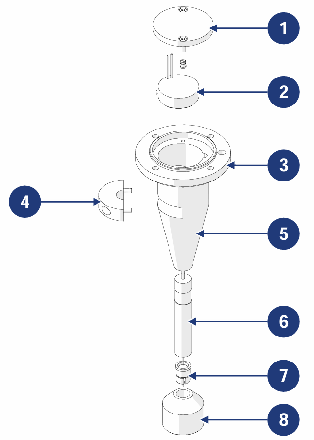
| POS. | DESCRIPTION |
|---|---|
| 1 | TOP CLOSURE CAP |
| 2 | CR2032 3V COIN CELL BATTERY HOLDER |
| 3 | COUPLING FLANGE |
| 4 | CLAMP |
| 5 | TOOL BODY |
| 6 | LASER POINTER |
| 7 | SPRING DAMPER |
| 8 | SPACER BRACKET |
Important
The bracket for mounting the Laser Tool in place of the robot tool is NOT supplied, as it varies for each robot and must be customised.
Tip
The use of the Laser Tool in combination with the ARS Dedicated Calibration Grid is the strongest and most accurate method for installing the FlexiVision One system
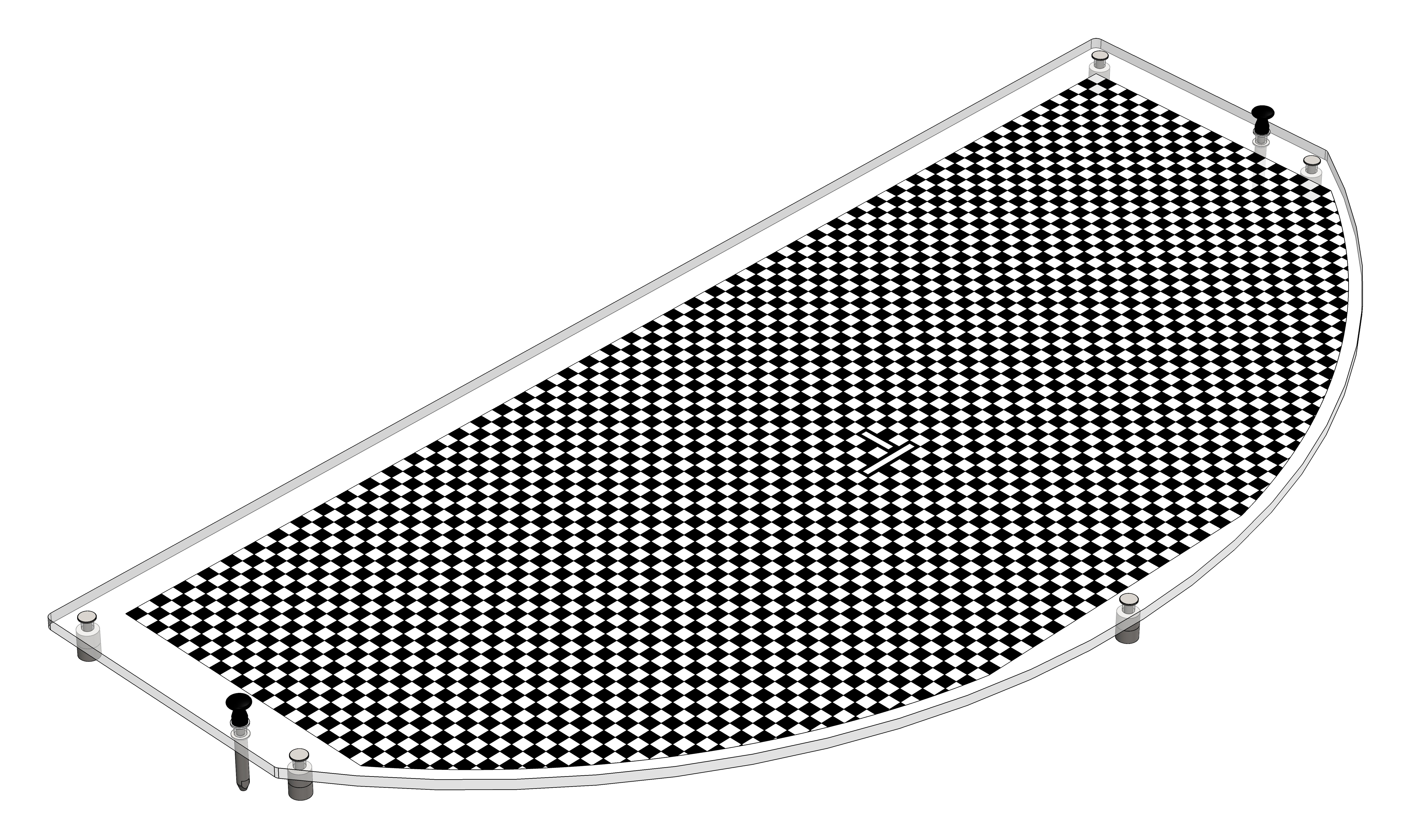
Calibration grid#
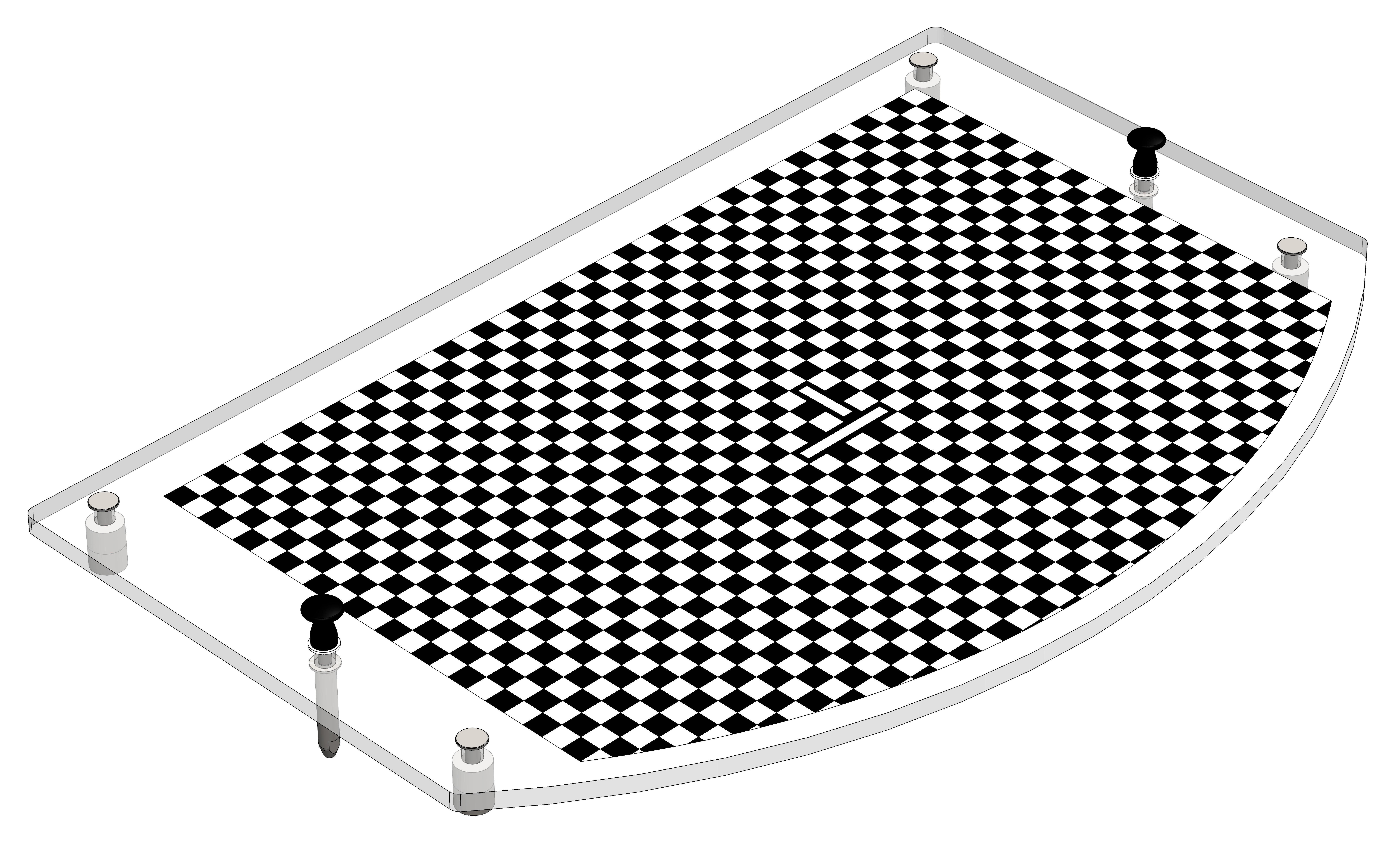
Excellent calibration is the basic requirement for the accuracy of the FlexiVision One system. Only high-precision calibration ensures that the coordinates detected by the camera (pixels) are accurately converted into the actual robot coordinates (millimetres), thus ensuring the success of the picking application.
Grid technical specifications#
Grid for FlexiBowl® 200
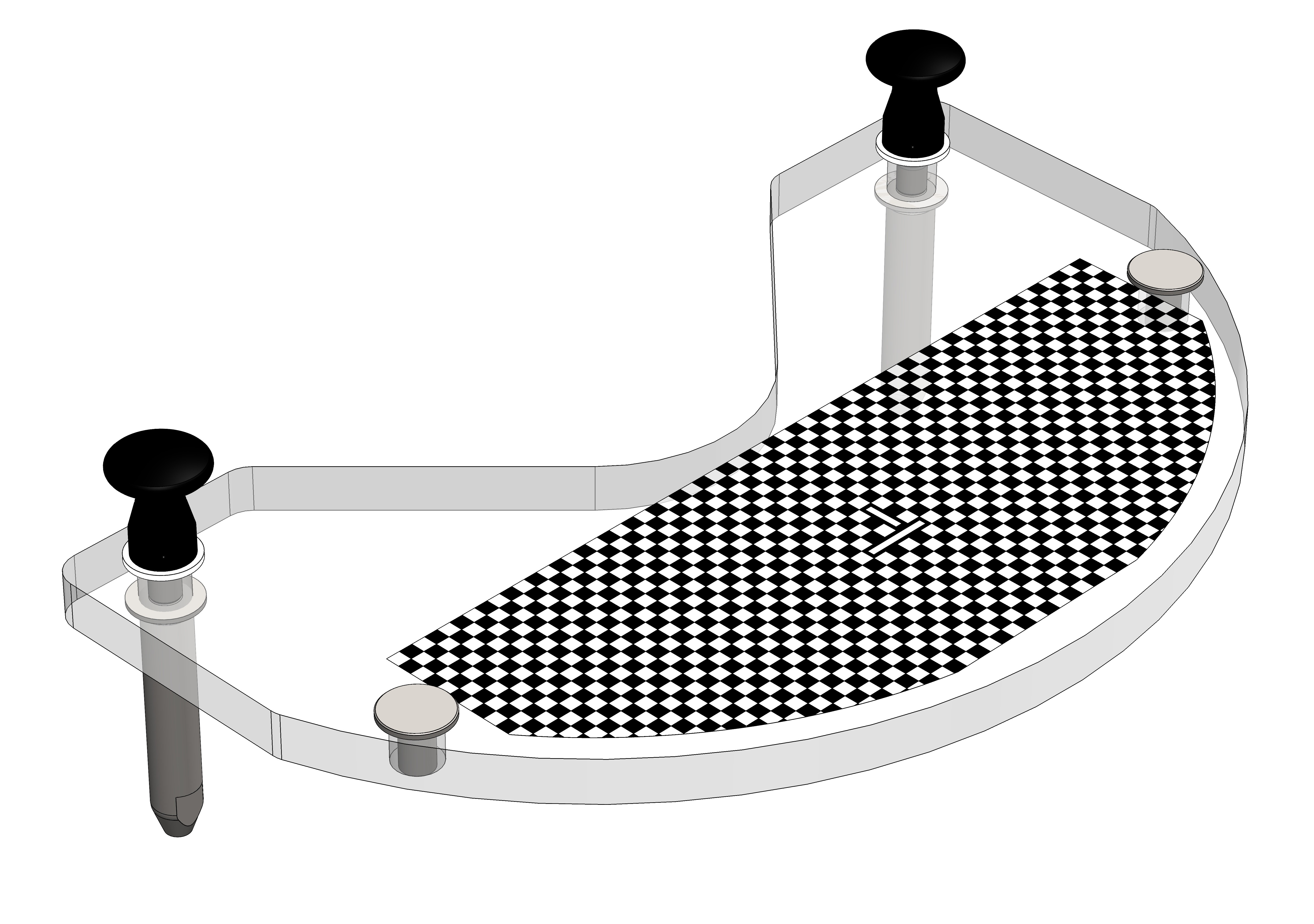
Grid for FlexiBowl® 350
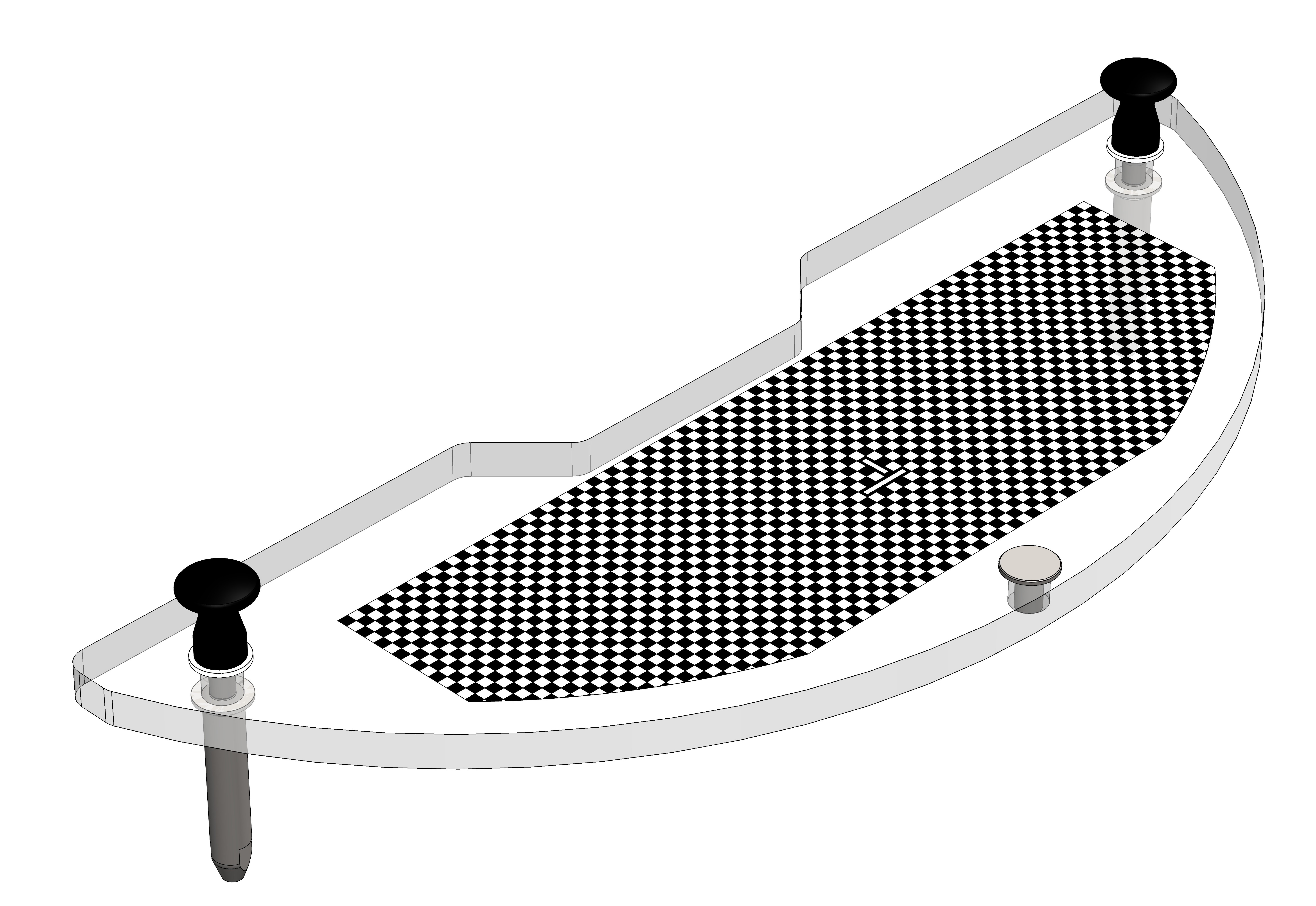
Grid for FlexiBowl® 500
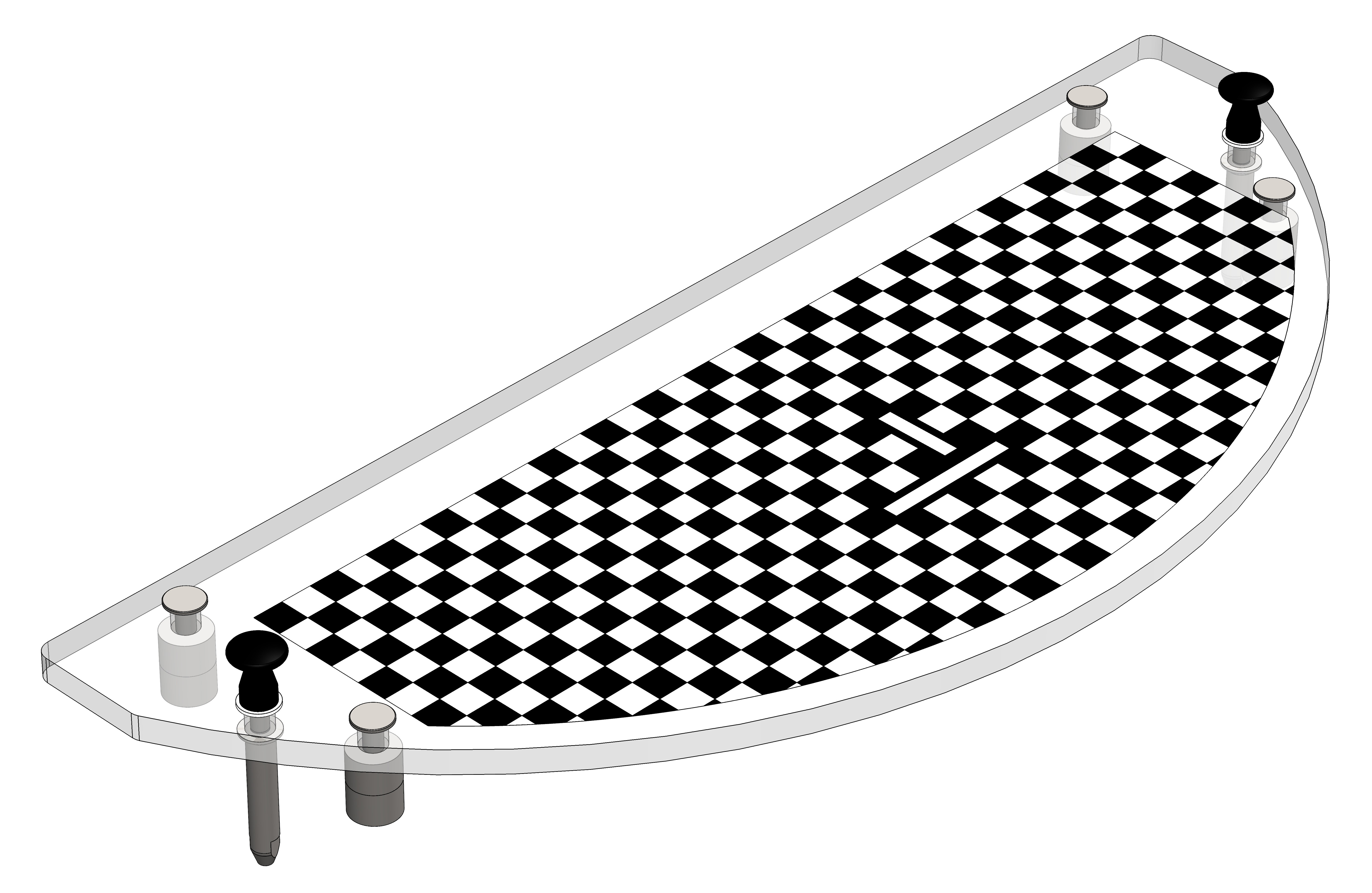
Grid for FlexiBowl® 650
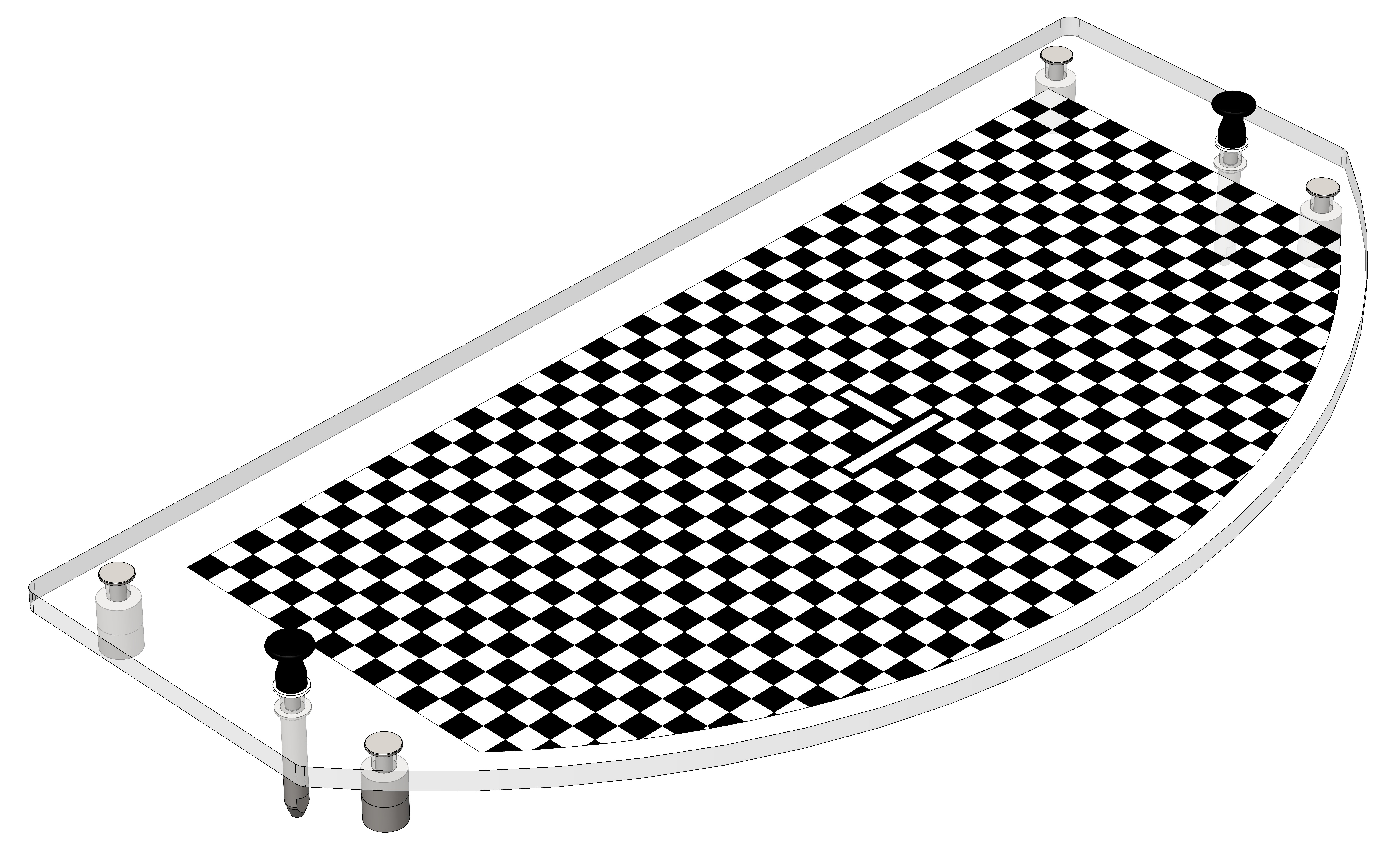
Grid for FlexiBowl® 800
Grid for FlexiBowl® 1200
For detailed information on calibration procedures, see section Camera Calibration.
Connections overview#
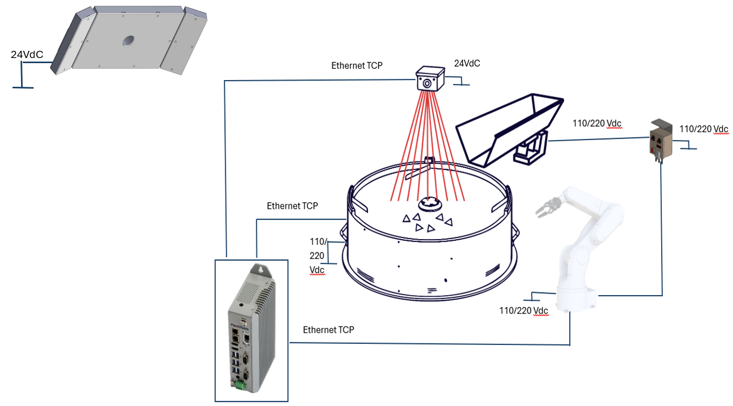
Complete connection diagram of FlexiVision One system with robot and FlexiBowl®
From |
To |
Connection |
|---|---|---|
Power grid |
FlexiBowl® |
110/230 Vac power supply |
Power grid |
Robot |
Power supply according to the specifications of the robot in your possession |
Power grid |
Camera |
24 Vdc power supply |
Power grid |
Illuminator (light) |
24 Vdc power supply |
Power grid |
Hopper Controller |
110/230 Vac power supply |
Hopper Controller |
Hopper |
Power supply and signal |
Robot |
Hopper Controller |
Digital I/Os |
VisionController |
Camera |
Ethernet TCP |
VisionController |
FlexiBowl® |
Ethernet TCP |
VisionController |
Robot |
Ethernet TCP |
For detailed wiring diagrams, see section Wiring and Connections.
Optional components#
Additional components available separately: