ROI Definition and Tolerances#
In this section, the Region Search and identification tolerances for the created model are defined. These parameters determine where and with what precision FlexiVision One will search for components during operation.
What is the Region Search? The Region Search is the area within which FlexiVision One will search and detect components to be picked.
Procedure#
After clicking ‘Next’ on the training page, the Define Robot Picking Limit Area Model page opens automatically.
Step 1: Area Definition#
1 |
On the Define Robot Picking Limit Area Model page, edit the box to delimit the search area |
2 |
Once the Region Search is correctly sized, click |
3 |
The Locator Model 1 Cam 1 page will open |
Tip
Size the area according to the robot’s actual working space, avoiding unreachable areas.
Tip
If you have any doubts during configuration, please consult the INFO key on the current page.
Locator Model interface overview#
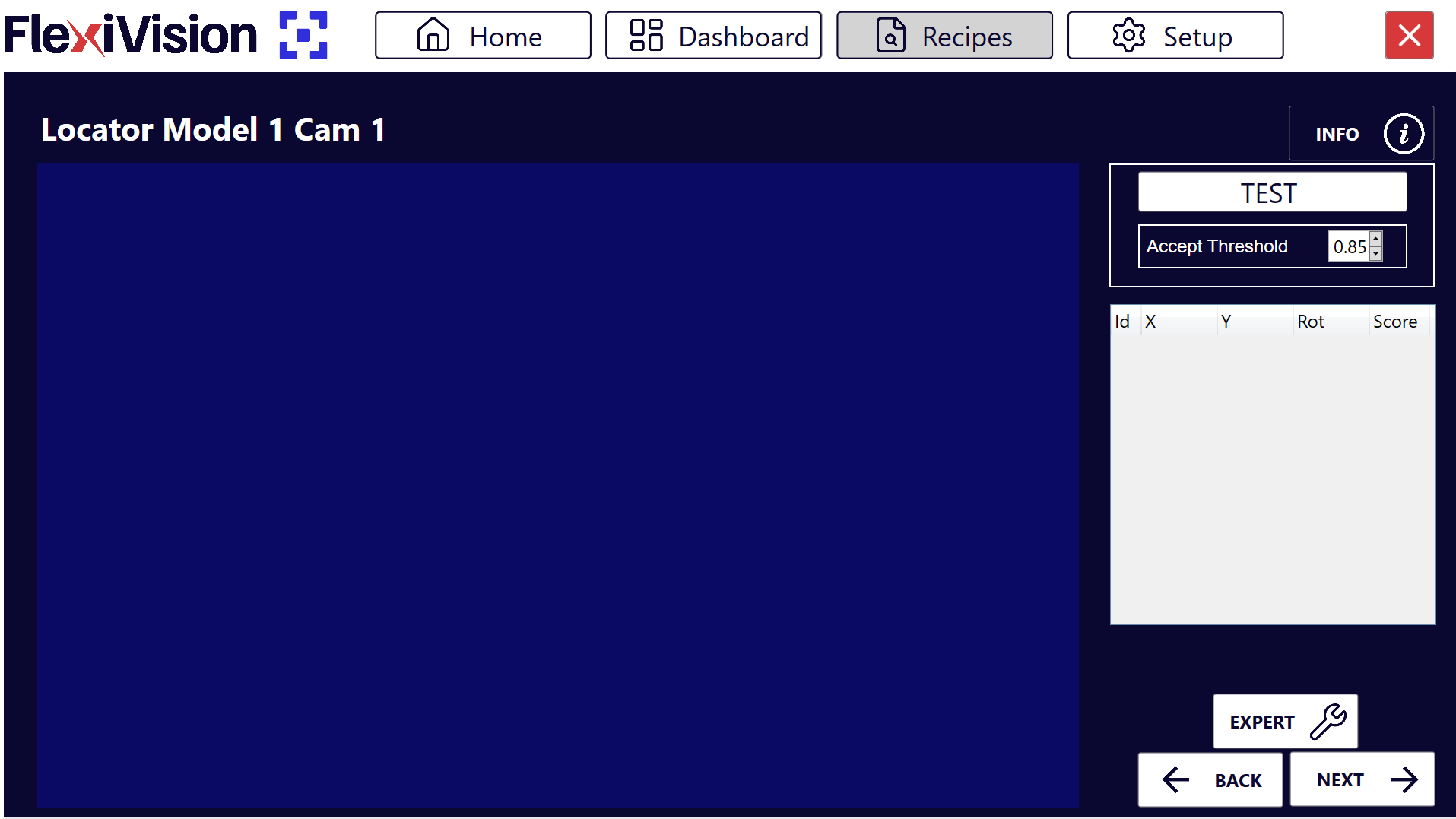
Parameter |
Description |
|---|---|
Test |
Performs a real-time identification test with the current parameters |
Accept Threshold |
Minimum fidelity threshold (score) that a component must have in order to be accepted |
Results Panel |
Panel showing all detected components with details (Id, coordinates, score) |
Video Tutorial#
Video tutorial explaining the subsequent Step 2 and Step 3:
Step 2: Scene Preparation#
4 |
Place other components in the vision area randomly around the reference component so as not to confuse them with it. Warning Do not touch the reference component used for training! And don’t lose sight of it! |
Step 3: Test Execution and Accept Threshold#
5 |
Click |
6 |
Observe how many components are detected and with which scores |
7 |
Change the Accept Threshold according to application needs Note What is the Accept Threshold? It’s the minimum degree of fidelity (score) that a detected component must have with respect to the reference model to be accepted.
|
 to run identification
Tip
Recommended iterative approach:
Start with Accept Threshold = 0.85
Run Tests and see results
If too many parts accepted (including false positives) → Increase threshold (e.g: 0.90)
If too few parts detected (good pieces discarded) → Decrease threshold (e.g: 0.80)
Repeat until the optimum value for the application is found
Goal: Find the highest possible value that detects all the good parts but rejects the worst ones.
Tip
If you have any doubts during configuration, please consult the INFO key on the current page.
Interpreting Results#
Display of detected components#
The Results panel shows all detected components that meet the Accept Threshold criteria:
Field |
Type |
Description |
|---|---|---|
Id |
Integer |
Progressive unambiguous identifier (0, 1, 2, …) |
X |
Millimetres |
X-coordinate of the component (reference origin of the calibration grid) |
Y |
Millimetres |
Y-coordinate of the component (reference origin of the calibration grid) |
Rotation |
Degrees |
Angle of rotation of the component (0-360°) |
Score |
Percentage |
Degree of fidelity compared to the reference model (0.00-1.00) |
Priority System
FlexiVision One by default automatically sorts all components identified by decreasing score:
Id 0 → Component with highest score (most similar to the reference model)
Id 1 → Second best component
Id 2 → Third best component
And so on…
Interpretation example#
Let’s suppose that these results appear after the Test:
Id |
X |
Y |
Rotation |
Score |
|---|---|---|---|---|
0 |
125.4 |
-45.2 |
15.3° |
0.92 |
1 |
-80.1 |
32.5 |
178.5° |
0.89 |
2 |
45.7 |
110.3 |
92.1° |
0.86 |
3 |
-150.2 |
-95.7 |
45.8° |
0.83 |
Interpretation:
Id 0: Best match (92%), will be picked first
Id 1: Good match (89%), second option
Id 2: Fair match (86%), third option
Id 3: Acceptable match (83%), fourth option
If Accept Threshold were 0.85:
Id 0, 1, 2 would be accepted
Id 3 would be rejected (score 0.83 < 0.85)
Finalisation#
Step 4: Cleaning and Continuation#
8 |
Remove all components from the area, except the reference component and the two objects at its sides Danger Do not move the reference component! Even when cleaning the scene, take care not to bump or move the reference component. Its coordinates are still needed for robot calibration in the final phase. |
9 |
Click |
See also
Proceed to the Clearances Configuration to define the clear areas.