Initial System Configuration#
This section guides the user through the complete configuration of the hardware and software components of the FlexiVision One system. It is essential to follow the steps in the order indicated to ensure proper operation of the system.
Note
Prerequisites
Before starting the software configuration, make sure that:
Mechanical installation of all components is completed (Mechanical Installation)
All cables are correctly connected (Wiring and Connections)
 #
#
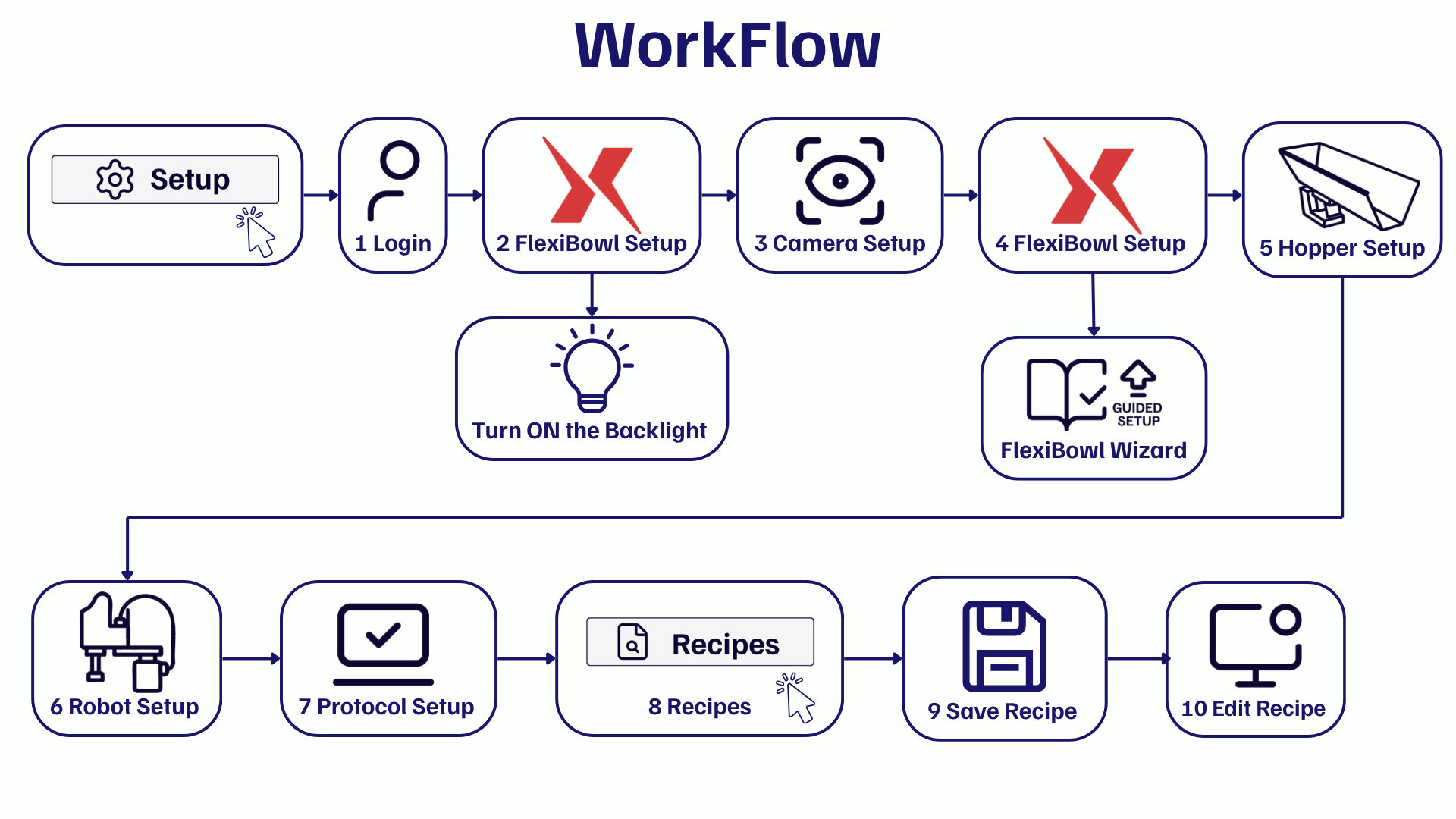
Overview of the setup process#
The initial setup process consists of seven main steps:
Enter the Licence Key supplied in the kit
Login - Access the software with user credentials
if Backlight included: Configure FlexiBowl® IP Address and Switch on Backlight
Camera Setup
FlexiBowl Setup - Connect and configure the FlexiBowl®
Hopper Setup
Robot Setup - Configure communication with the robot
Protocol Setup - Configure protocol parameters
Rename and Save the Basic Recipe - Application profile configuration
Warning
Order of steps
The order of the setups is important! Do not skip steps or change the sequence, as some setups depend on previous ones.
Preliminary operations#
Important
The first step before starting the FlexiVision One software is to enter the license key supplied with the kit.
Login to the system#
When the FlexiVision One software is started, the Home page is displayed.
0 |
Click Setup |
1 |
Select the user ENGINEER from the drop-down menu at the top right. |
2 |
Enter the password ‘3’. |
3 |
Click the LOGIN button to access the interface. |
Tip
User management
FlexiVision One supports multiple user profiles with different permission levels:
ARS
Engineer
Technician
Operator
Switch on the Backlight if included#
After the first login, if you need to activate your FlexiVision One licence, follow these steps:
4 |
From the software home page, click |
5 |
On the SETUP page, identify and click the FlexiBowl® Setup icon Setup Page
|
6 |
The FlexiBowl® Setup screen opens |
7 |
Enter the FlexiBowl® IP address (default: |
8 |
After entering the IP, click the button Connection Test |
9 |
The system performs a communication test (ping) to the FlexiBowl® |
10 |
Observe the Status indicator:
|
11 |
Click the button |
12 |
A window opens with the configurable parameters of the FlexiBowl® |
13 |
Turn on the backlight by ticking the “Light ON” box |
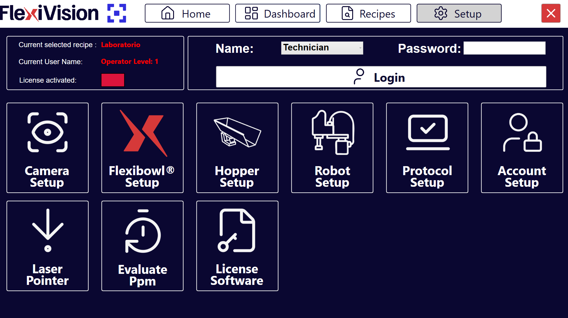
Hardware components configuration#
Once the preliminary steps have been completed, proceed to configure the hardware components in the following order.
All hardware setups are accessible from the software’s central SETUP page.
14 |
From the main menu, click |
15 |
Icons for the different components to be configured are displayed |
16 |
Click the icon of the desired component to access its specific configuration |