Camera Setup#
This section describes the procedure for configuring and testing the industrial camera of the FlexiVision One system. The correct camera setup is crucial for capturing quality images.
Note
Prerequisites
Before proceeding, make sure that:
The camera has been mechanically installed at the right distance
The camera’s Ethernet cable is connected to the VisionController
The camera is powered (via PoE or external power supply)
FlexiBowl® is configured and the backlight is working (for capture test)
Access to Camera setup#
1 |
From the home page of the software, click |
2 |
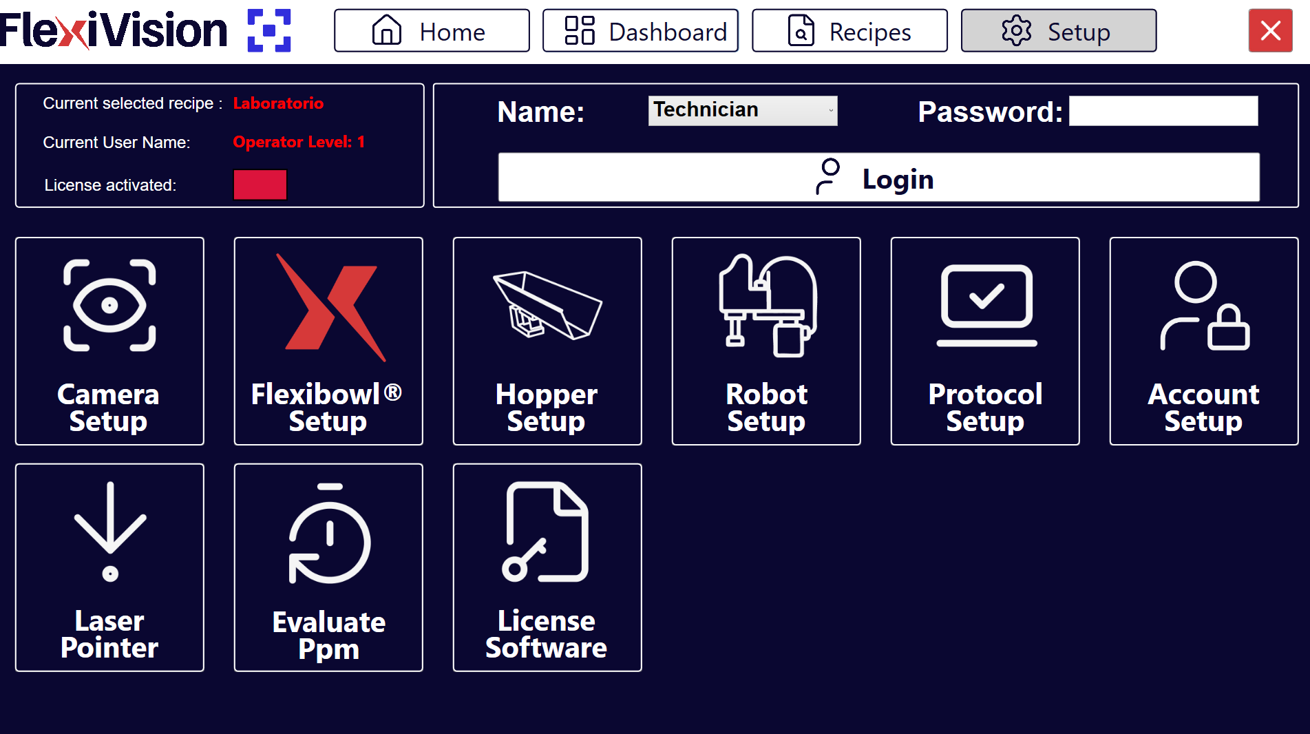
On the SETUP page, identify and click the Camera Setup icon Setup page
|
3 |
The camera configuration page opens |
Camera Setup Interface Overview#
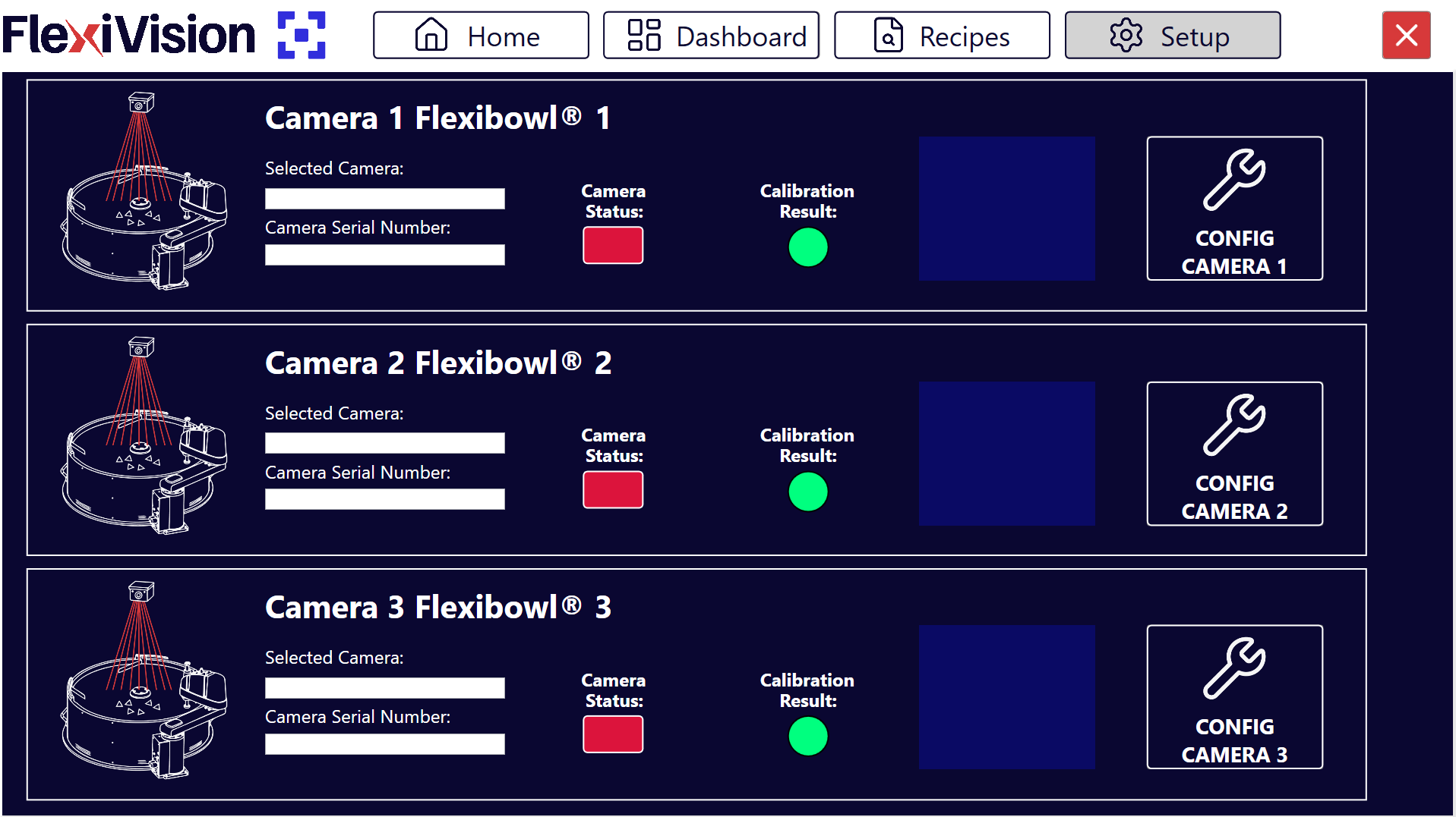
The Camera Setup page has three main information boxes and a configuration area:
Section |
Description |
|---|---|
Selected Camera |
Shows the identification of the currently selected camera. It is shown automatically when FlexiVision One is started. |
Camera Serial Number |
Displays the unique serial number of the connected camera |
Status |
Indicates the connection status |
Calibration Result |
Shows the calibration result of the camera |
Config Camera |
Button to open the detailed configuration page |
Note
For the sake of convenience and consistency, we recommend matching the camera number with the corresponding FlexiBowl®:
✅ Camera installed above FlexiBowl® 1: CAM-CIC-5000-20G-12345 > Select Camera 1 FlexiBowl® 1
Warning
If the camera is not visible when FlexiVision is first opened, see Troubleshooting for Camera Setup
Next steps#
Once the camera Setup is complete, proceed with: