Hopper Setup#
This section describes the procedure for configuring the hopper. The Hopper is the component that automatically feeds parts to the FlexiBowl® when the level drops below a minimum threshold.
Important
Operating logic
FlexiVision manages the hopper activation logic. It will in fact send the string Hopper;signalnumber;time when it considers activation necessary.
Note
Prerequisites
Before proceeding, make sure that:
The Hopper has been mechanically installed
The electrical connections have been made (control and power signals)
The FlexiBowl® is already connected
Preparing the Physical Setup#
0 |
Remove the calibration grid and restore the initial layout:
|
Accessing Hopper configuration#
1 |
From the software main page, click |
2 |
On the SETUP page, locate and click the Hopper Setup icon Setup Page
|
3 |
The Hopper configuration page opens |
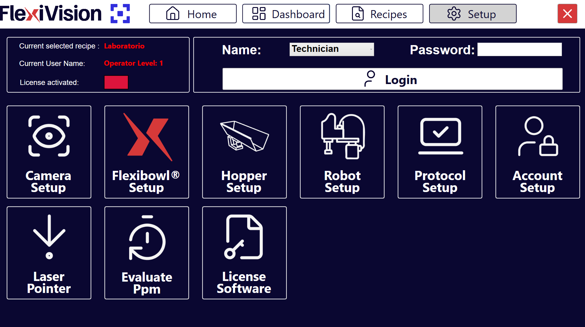
Hopper Setup Interface Overview#
The Hopper Setup page has several sections for configuring the operating parameters of the various hoppers:
Section |
Description |
|---|---|
Enable Hopper |
Switch to enable/disable the use of the Hopper in the system |
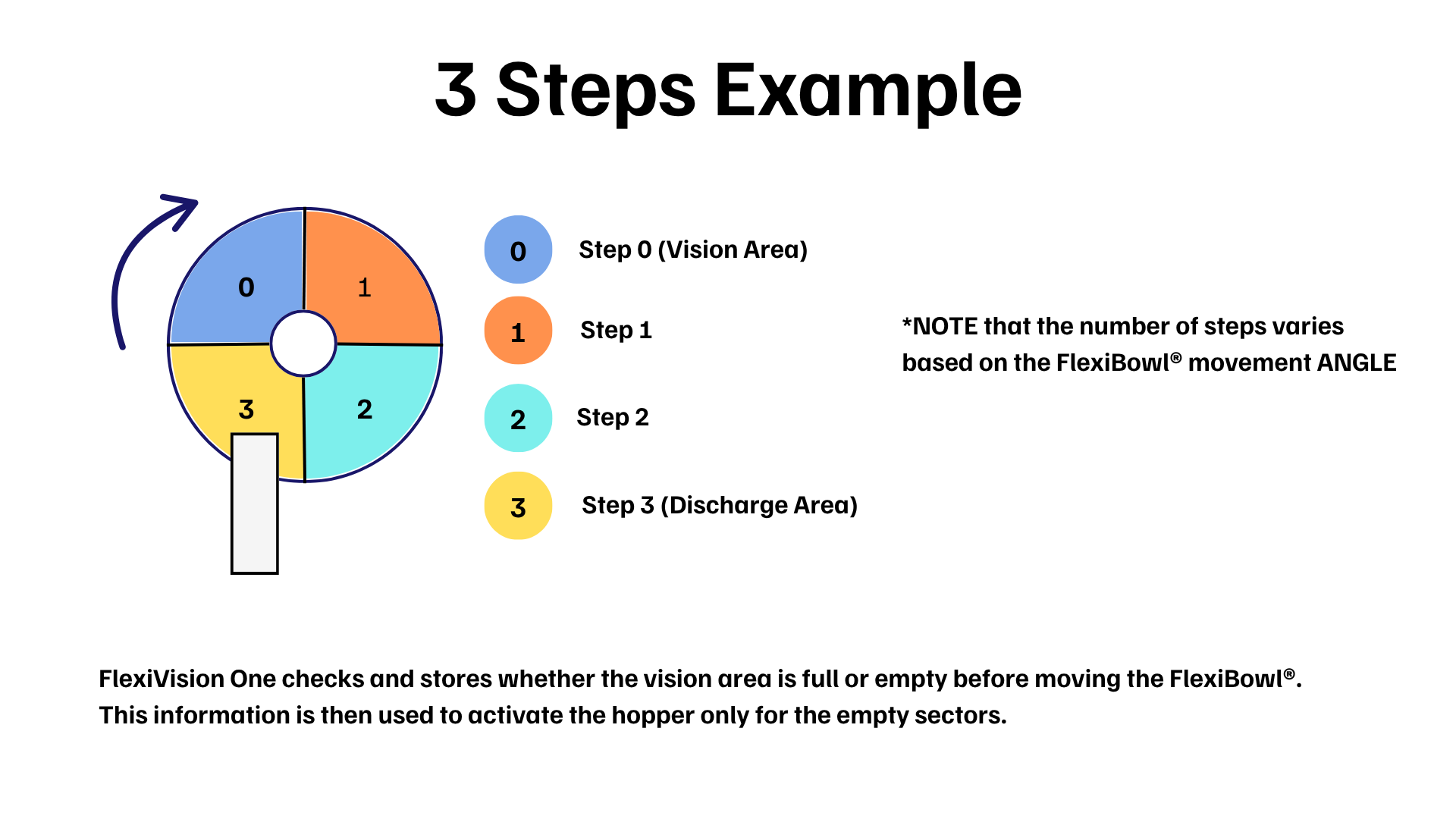
Steps |
Number of required sequences with which the section of the disc that is currently in the vision area arrives below the hopper unloading area |
Time |
Duration of hopper activation in milliseconds |
Signal |
Number of the digital signal used to control the Hopper |
Config Hopper |
Button to configure the hopper (to be used later) |
Hopper configuration#
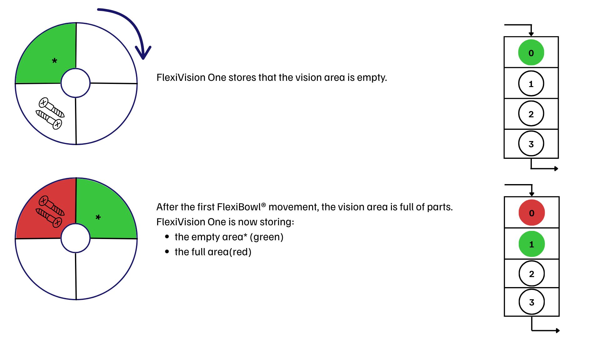
The hopper configuration allows you to manage the automatic filling of components on the FlexiBowl® disc. The system uses the vision to determine when the filling level is insufficient and to activate the hopper.
Step 1: Accessing the Configuration#
1 |
Click Hopper Setup Page
|
2 |
In the Signal field, enter the number of the digital signal (DO - Digital Output) used to control the Hopper Warning It is essential to enter the correct signal number:
|
3 |
Tick the Enable Hopper X box to activate the corresponding hopper. Important Only enable the Hopper if the device is correctly installed |
4 |
Click the Config Hopper X button to access the specific configuration |
Step 2: Defining the Control Area#
In this step, the portion of the disc that the camera needs to monitor for unloading is defined.
5 |
Change the blue box on the screen to frame the area where the components will be detected. |
Tip
If you have any doubts during configuration, please consult the INFO key on the current page.
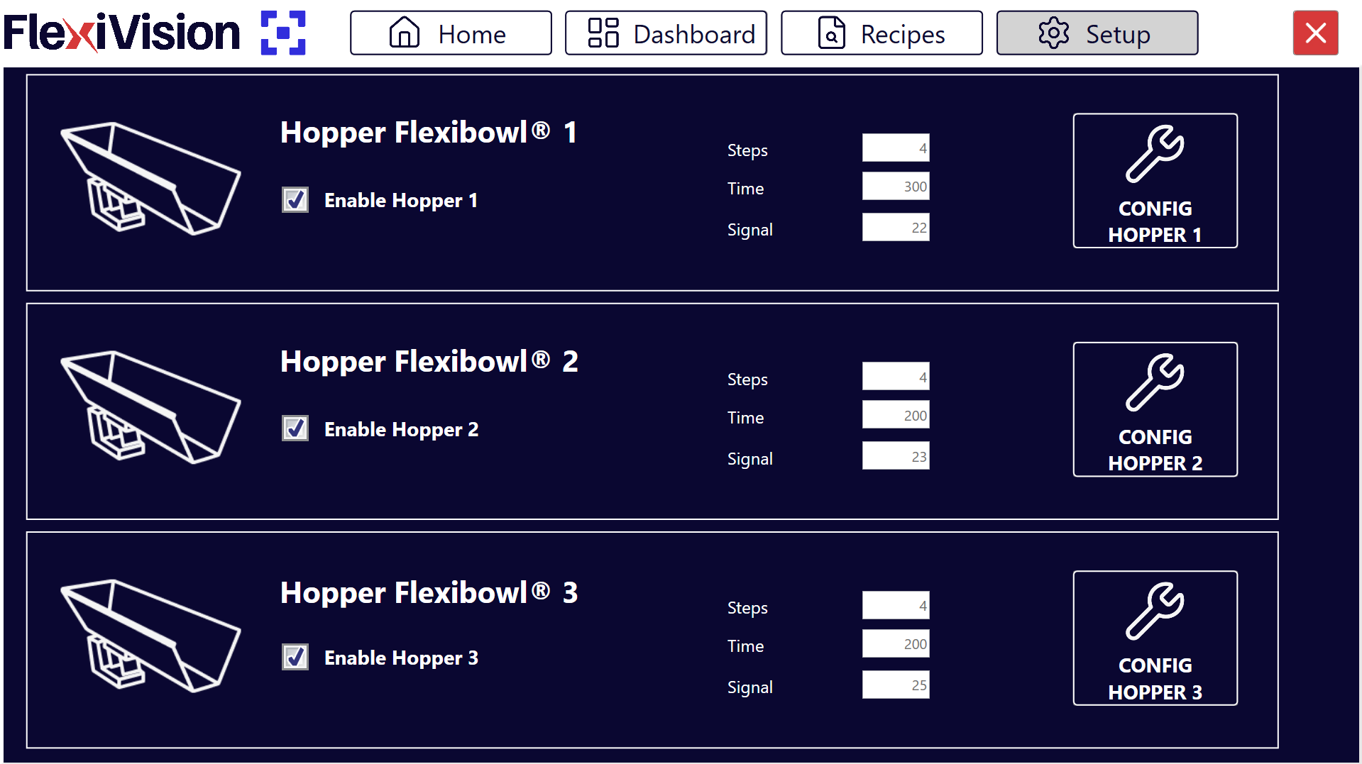
Step 3: Definition of Threshold Values#
6 |
Click Define Value Hopper Cam Page
|
7 |
Remove all components from the vision area and click the first CAPTURE button. |
8 |
Position the minimum number of components you wish to keep in the vision area. If the number drops below this threshold, the hopper will be activated. |
9 |
Click the second CAPTURE button. |
10 |
By clicking |
11 |
Remove some pieces and click |
12 |
Look at the result indicator:
|
 in the Expression Builder, the system automatically calculates the Mean and Standard Deviation values.
 .
.Note
Hopper Fill Threshold
The Hopper Fill Threshold parameter defines the filling percentage threshold of the vision area below which the hopper is automatically activated.
The value of 100% corresponds to the amount of pieces acquired during the second CAPTURE (full area). Consequently, a 50% threshold corresponds to half of that amount.
The system automatically sets the initial value to 70%, which is a good balance for most applications.
Ongoing modification
It is possible to adjust the threshold without repeating the capture procedure:
To unload fewer pieces → reduce the percentage (e.g. 50%) and click AUTO
To unload more pieces → increase the percentage (e.g. 85%) and click AUTO
Tip
If you have any doubts during configuration, please consult the INFO key on the current page.
Step 4: Operational Parameters#
Return to the main Hopper Setup screen to define the mechanical behaviour.
Parameter |
Description and Procedure |
|---|---|
Steps |
Number of FlexiBowl® feeds (sequences) required to bring parts from the vision area to the hopper unloading area. |
Time |
Milliseconds of hopper activation. Recommended value: 100 – 1000 ms (Average: 500 ms). Adjust by ±50 ms according to the desired flow. |
Tip
The activation time depends not only on the set value, but also on the volume of components currently in the hopper tank. It is essential to maintain a constant load for an even flow.
Tip
The Time value is closely related to the hopper loading volume:
With the hopper full, there will be more parts in the unloading area
With the hopper half-full, there will be fewer parts in the unloading area
Important
In general, it is important never to exceed the maximum load of the hopper used.
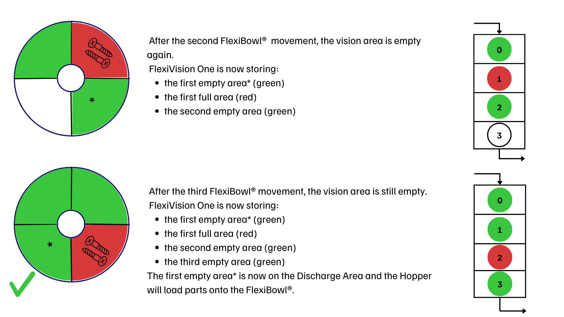
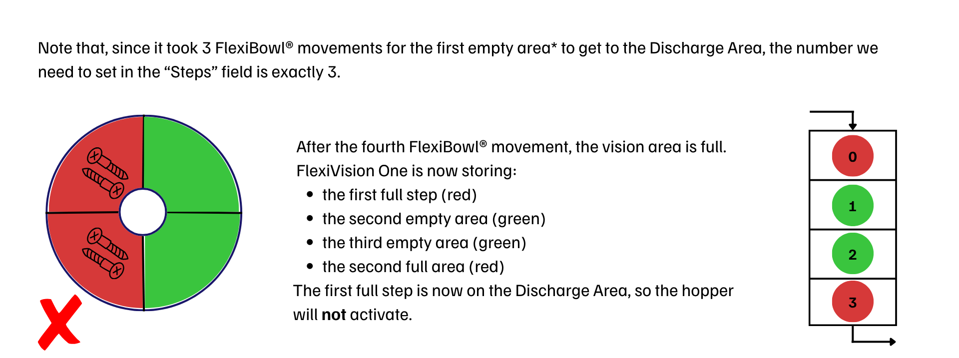
Calculate the Steps Parameter#
Saving Configuration#
Warning
Saving recipe mandatory
At the end of the Hopper configuration:
Verify that all parameters are configured correctly:
|
|
Return to the main page |
|
Click |
|
Confirm saving |
IMPORTANT: Any changes made are stored ONLY if the recipe is saved correctly before exiting or changing page.
Without saving, all Hopper setups will be lost when FlexiVision One is closed!
Next steps#
Once the Hopper Setup is complete (or skipped if not present), proceed with: