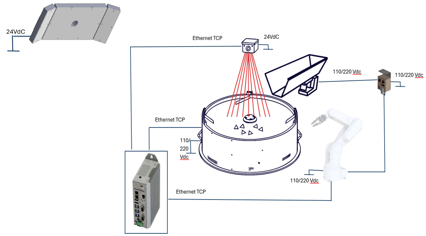
Wiring and Connections#
From |
To |
Connection |
|---|---|---|
Power grid |
FlexiBowl® |
110/220 Vdc power supply |
Power grid |
Robot |
Power supply according to the specifications of the robot in your possession |
Power grid |
Camera |
24 Vdc power supply |
Power grid |
Illuminator (light) |
24 Vdc power supply |
Power grid |
Hopper Controller |
110/220 Vdc power supply |
Hopper Controller |
Hopper |
Power supply and signal |
Robot |
Hopper Controller |
Digital I/Os |
VisionController |
Camera |
Ethernet TCP |
VisionController |
FlexiBowl® |
Ethernet TCP |
VisionController |
Robot |
Ethernet TCP |
Wiring wizard#
Step |
Action |
|---|---|
1 |
Connect the FlexiBowl® power supply. |
2 |
Connect the Hirose 24V power cable to the Camera. |
3 |
Connect the FlexiBowl® to the VisionController with Ethernet cable. |
4 |
Connect the Camera to the VisionController (PC) with Ethernet cable. |
5 |
Connect the Robot to the VisionController with an Ethernet cable. |
6 |
Connect compressed air to the FlexiBowl®. |
7 |
If present, connect the hopper to its controller |
8 |
If present, connect the robot to the hopper controller (Digital I/Os) |
9 |
If present, power the hopper controller (110/220 V depending on the option chosen when purchasing the vibrating hopper base) |
10 |
Turn on the FlexiBowl® AC switch (position “I”). The READY LED is ON. |
11 |
Switch on all other devices |
Illuminator wiring#

Parameter |
Requirement / Action |
|---|---|
Voltage |
24V DC (±10%). Minimum operating voltage: 20V DC on the light input. |
Connector |
M12 Male. Note To connect the toplight, you can also purchase its power cable. |
Connector pinout |
Pin 1: +24V (brown) — Pin 3: GND (blue) — Pin 4: STROBE PNP (black) |
STROBE mode (PNP) |
5V to 24V for 100% switch-on. 0V to 1V for 100% switch-off. |
CONTINUOUS mode |
Pin 1 (+24V) and Pin 3 (GND) connected; Pin 4 (PNP) connected to Pin 1. |
Voltage drop (M12 cable, 10m) |
1.15V @ 5A — 2.3V @ 10A — 3.5V @ 15A — 4.6V @ 20A (max 20A) |
Shielding |
Use shielded cables to reduce electromagnetic interference (EMI). |
Warning
Electrical Safety
Observe the indicated supply voltages and connection terminals.
Do not modify or disassemble the product.
Do not connect or clean the appliance when it is live.
Do not stare at the light source.